Advertisement
Quick Links
Advertisement

Subscribe to Our Youtube Channel
Related Manuals for Core Health & Fitness Nautilus NN-B7506


Summary of Contents for Core Health & Fitness Nautilus NN-B7506
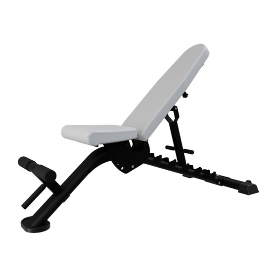
- Page 1 CORE HEALTH & FITNESS MULTI-ADJUSTABLE BENCH OWNER'S MANUAL...
-
Page 2: Table Of Contents
TABLE OF CONTENTS IMPORTANT SAFETY INSTRUCTIONS ........................2 IMPORTANT LABEL LOCATIONS ..............4 WEIGHTS & DIMENSIONS ..............ASSEMBLY ........................6 SUPPORT & SERVICE ........................8 Page 1... -
Page 3: Important Safety Instructions
IMPORTANT SAFETY INSTRUCTIONS WARNING! Before using this product, it is essential to read the ENTIRE Owner’s Manual and ALL installation instructions. The Owner’s Manual describes equipment assembly and instructs members on how to use correctly and safely. Read all warnings posted on the machine. Health related injuries may result from incorrect or excessive use of exercise equipment. - Page 4 Ensure all adjustment and locking features are properly secured before using the equipment. When adjusting any seat, knee stabilization pad, range of motion limiter, foothold pad or any other type of adjuster, make certain that the adjusting pin is fully engaged in the hole to avoid injury. If any of the adjustment devices are left projecting, they could interfere with the user’s movement.
-
Page 5: Important Label Locations
IMPORTANT LABEL LOCATIONS This page shows the location of the warning labels and communication stickers placed on the equipment as part of the manufacturing process. It is critical that owners maintain the integrity and placement of these stickers. If you find any stickers missing or damaged the replacement numbers are shown on the support site and following pages. - Page 6 N12-8024 DECAL, NAUTILUS,DECO, 0.91” X 3.90” support.nautilusstrength.com 1-800-503-1221 PN:731-7920 731-0512 731-7920 STICKER,CAUTION,PINCH STICKER,WARNING,NP STANDARD INSTRUCTIONS 050-2141 LABEL, WARNING, SHEAR POINT Notice: images are not to scale Page 5...
-
Page 7: Assembly
ASSEMBLY Metric Steel Bolts Torque Specifications All equipment MUST be secured Bolt Size Thread Pitch Torque, N-m (lbs-ft) (bolted and tightened) to a solid, level 1.25 10 to13.5 (8 to10) surface, using all of the anchoring 1.25 25.5 to 28.5 (19 to 21) holes provided, to stabilize and eliminate rocking or tipping over. - Page 8 PROCEDURE 110-3955 731-0367 1. Install the rear stabilizer assembly into the bench frame, then use an allen key to secure the stabilizer using a M10 flat washer and a M10 x 25mm button head cap screw. 2. Use an allen key and an open- ended wrench to finish securing the stabilizer to the frame using the end plate, two of the M10...
-
Page 9: Support & Service
SUPPORT & SERVICE For Technical Support, Service, Parts Orders or any Customer Service needs, please contact us direct by phone, email, or through our 24 hour support site: GLOBAL SUPPORT CENTER 4400 NE 77th Avenue, Suite 300 Vancouver, WA 98662 Tel: (360) 326-4090 •... - Page 10 THIS PAGE INTENTIONALLY BLANK Page 9...
- Page 11 THIS PAGE INTENTIONALLY BLANK Page 10...
- Page 12 © 2021 CORE HEALTH & FITNESS LLC PART NUMBER 620-8851, REV B All rights reserved. Star Trac, the Star Trac logo and StairMaster are registered trademarks of Core Health & Fitness, LLC. Schwinn and Nautilus are registered trademarks of Nautilus Inc. used under license to Core Health & Fitness LLC. Throwdown is a registered trademark of Throwdown Industries, LLC.
Need help?
Do you have a question about the Nautilus NN-B7506 and is the answer not in the manual?
Questions and answers