
Related Manuals for Velleman-Kit HIGH-Q K8040


Summary of Contents for Velleman-Kit HIGH-Q K8040
- Page 1 HIGH-END MONO MOSFET POWER AMPLIFIER Total solder points: 299 5 ⌧ advanced Difficulty level: beginner 1 K8040 K8040 ILLUSTRATED ASSEMBLY MANUAL H8040IP-2...
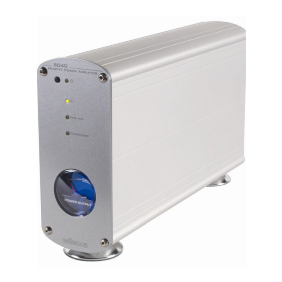
- Page 3 Features & specifications Features : no compromise high-end design ideal to place next to the speaker (short wires to the speaker) auto-power on possibility when input signal is sensed auto-standby function when no input signal is sensed exclusive, high finish, solid aluminium enclosure high quality D-MOS IC output stage total of 40.000µF power supply capacitors relay-less speaker DC protection...
- Page 4 Assembly hints 1. Assembly (Skipping this can lead to troubles ! ) Ok, so we have your attention. These hints will help you to make this project suc- cessful. Read them carefully. 1.1 Make sure you have the right tools: •...
- Page 5 Assembly hints * Typographical inaccuracies excluded. Always look for possible last minute manual updates, indicated as ‘NOTE’ on a separate leaflet. 1.3 Soldering Hints : 1- Mount the component against the PCB surface and carefully solder the leads 2- Make sure the solder joints are cone-shaped and shiny 3- Trim excess leads as close as possible to the solder joint...
- Page 6 Construction CONSTRUCTION The unit consists of one main PCB with all the components including transformer and power supply. Tip: The pictures on the packaging can be used as a guideline. However, due to possible modifications they are not 100% reliable. Mount the components in the order described: 1.
- Page 7 construction R28 : 2K2 0.6W (2 - 2 - 2 - 9) 6. IC sockets. Watch the position R29 : 2K2 0.6W (2 - 2 - 2 - 9) of the notch! R30 : 0R R31 : 15K (1 - 5 - 3) IC1 : 8p R32 : 100K (1 - 0 - 4)
- Page 8 Construction 10. RCA connectors. Mount them 12. Terminal blocks straight and against the PCB SK3: 3p "Mains in" SK4: 3p "Mains transformer" SK1: MJ-523AG/R SK2: MJ-523AG/B Tip: A red and a black type are delivered with the kit, if you bought 2 amplifiers for stereo then one amplifier can be built with red connectors (right amp.) and one with the black...
- Page 9 construction 14. Coil 16. Voltage regulator. The back side corresponds to the thick line. L... VR1 UA7805 VR... This coil will have to be made by yourself. Use the supplied copper wire (1.5mm) with the kit. 17. Triac. The back side Wind this wire round a 8mm drill or corresponds to the thick line.
- Page 10 Construction 20. Power electrolytic capacitors. 21. IC’s. Watch the position of the notch ! Check the polarity ! C31: 10.000µF C32: 10.000µF C33: 10.000µF C34: 10.000µF C... IC1: VK8040 (PIC12C508) IC2: CA258 or eq. IC3: MOC3041 / KP3020 22. Mounting front LED’s. Check the polarity ! Short lead = Cathode or - ! CAUTION: After bending the...
- Page 11 construction 23. Mounting the Power IC IC4: TDA7293 Mount the support plate onto the IC as shown in the drawing. Put a drop of silicone compound on both sides of the mica isolator. Also check the position of the plastic isolator A. ATTENTION : The bolt should be inserted on the side of the IC holder with the countersunk opening B ! Drop of heat conductive...
- Page 12 Construction 24. Mounting the power transformer and mains voltage selection Mount the transformer as in the drawing (see also the picture on the packaging) Use the supplied straps (4 pcs) to fix the transformer. Primary windings (MAINS) connection: Check the table on the PCB for the correct voltage selection and connect the wires : For 230V (220V to 240V), edge orange, then brown and black.
- Page 13 Enclosure preparation 25. Enclosure preparation Cut the thread in the holes for the enclosure feet in one of the alu- minum profiles, using the supplied special M4 screw as a tap. FIG. 1 Mount the feet on the aluminum profile, using two M4 hexagonal Allen screws.
- Page 14 Enclosure preparation Position the main PCB in the aluminum profile that is prepared with the feet. Mark the center position of the three fixation holes on the aluminum. A reference indication is also on the PCB edge. FIG. 4 Remove the pcb and use a knife or a screwdriver to scratch the paint from the aluminum fixation, from the hole closest to the back end.
- Page 15 Enclosure preparation Using an ohmmeter, measure between the edge of the aluminum profile and the back spacer, if there is a good electric contact (less then 10 ohm). If not, repeat the above step to remove the paint under the spacer. FIG.
- Page 16 Final assembly 26. final PCB mount RE-CHECK CAREFULLY THE PCB FOR MOUNTING AND SOLDERING ERRORS! Mount the pcb into the enclosure, check the position of the power IC. The IC support must fit onto the previously inserted hexagonal bolts. Make sure there is silicone compound between the IC support and the enclosure! Glue the included insert C between the transformer and housing.
- Page 17 Final assembly 27. Speaker and mains connector assembly Prepare the wiring of the mains connector like in the drawing. First mount the switch into the mains connector assembly. Do not forget to isolate the soldering connections using a piece of shrink tube. Use the supplied 0.5mm wire: Blue for Neutral Brown for Live...
- Page 18 Final assembly 28. Final assembly and connection Solder a 15cm (2.5mm) wire to the LS connectors. Black = negative, Red= positive, use a shrink tube to isolate the connection. Solder a spade terminal to the other end, do not forget the terminal isolation. 15cm Mount (insert) the mains connector onto the rear panel.
- Page 19 Final assembly Mount the rear panel onto the enclosure, using two M4 Allen screws. Connect the speaker wires to the speaker output tabs. Check the polatity! Black= LS-, Red= LS+. DO NOT CONNECT THE MAINS WIRING WITH THE PCB YET! 29.
- Page 20 Test 30. Test 21. Mains voltage connection Check again all connections of transformer and mains preparation Connect the mains wires to the mains connector SK3, Blue= Neutral, green/ yellow= Earth. Connect a 60W light bulb in series with the Live (Brown wire) and the Live Connect a 10cm blue wire to the connection on the PCB.
- Page 21 Test Test continued: • Now push the DC protection test button SW2, the bulb should light if the button is pressed. Be careful not to touch any exposed live parts. • Disconnect the mains plug. • Now the brown Live wire can be connected directly to the connector SK3.
- Page 22 BRIDGE RS603 Mains in from 2A fuse + switch UA7805 TIC246M 10.000uF/50V 10.000uF/50V Transfo Prim Power meter 25VAC / 2A 4.7R / 10W +35V 20V 1.3W 100K 100n 1N4148 JGND 100R 10µ 10µ 100n 1µ 470R +35V -35V 100n 2K2 / 0.6W DC prot.
- Page 23 32. PCB...
- Page 24 VELLEMAN KIT NV Legen Heirweg 33 9890 Gavere Belgium Europe Info ?: http://www.velleman.be Modifications and typographical errors reserved © Velleman Kit nv H8040IP - 2009 - ED2 5 4 1 0 3 2 9 4 1 6 7 7 5...
Need help?
Do you have a question about the HIGH-Q K8040 and is the answer not in the manual?
Questions and answers