
Related Manuals for Velleman-Kit K2572


Summary of Contents for Velleman-Kit K2572
- Page 1 Total solder points: 42 Difficulty level: beginner 1 advanced UNIVERSAL STEREO PRE - AMPLIFIER K2572 ILLUSTRATED ASSEMBLY MANUAL H2572IP-1...
-
Page 2: Specifications
Features & Specifications Specifications: Power supply: 10 - 30V DC maximum, stabilized. Current absorption with out charge : typ. 5mA. Adjustable gain : 40dB max. Frequency range : 40Hz - 30KHz (-3dB). IN-L Output impedance : 1KΩ. Max. Input voltage : 50mVrms (500mVrms) Dimensions : 44 x 65mm / 1,7”... -
Page 3: Assembly Hints
Assembly hints 1. Assembly (Skipping this can lead to troubles ! ) Ok, so we have your attention. These hints will help you to make this project successful. Read them carefully. 1.1 Make sure you have the right tools: • A good quality soldering iron (25-40W) with a small tip. - Page 4 Assembly hints 1.3 Soldering Hints : 1- Mount the component against the PCB surface and carefully solder the leads 2- Make sure the solder joints are cone-shaped and shiny 3- Trim excess leads as close as possible to the solder joint REMOVE THEM FROM THE TAPE ONE AT A TIME ! AXIAL COMPONENTS ARE TAPED IN THE COR- RECT MOUNTING SEQUENCE !
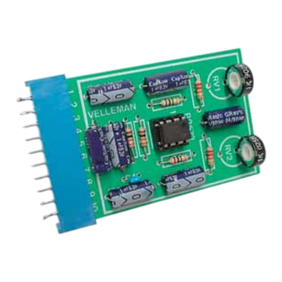
- Page 5 Construction 1. Resistors 3. Ceramic Capacitor 5. Potentiometers R... RV... RV1 : 1K C ... RV2 : 1K : 100nF (104, u1) R1 : 22K (2 - 2 - 3 - B) R2 : 22K (2 - 2 - 3 - B) R3 : 1MΩ...
- Page 6 7. Use Ten connections are provided on the pcb to connect the print with a device. These connections are identical to those of the RIAA preamplifier K25736 and in case you use the connectors included in this kit, you may interchange the two prints.
- Page 7 8. PCB...
- Page 8 VELLEMAN Components NV Legen Heirweg 33 9890 Gavere Belgium Europe www.velleman.be www.velleman-kit.com Modifications and typographical errors reserved © Velleman Components nv. H2572IP - 2003 - ED1 (rev 1.0) 5 4 1 0 3 2 9 3 1 0 1 2 7...
Need help?
Do you have a question about the K2572 and is the answer not in the manual?
Questions and answers