
Related Manuals for Velleman-Kit K4004B


Summary of Contents for Velleman-Kit K4004B
- Page 1 Total solder points: 136 Difficulty level: beginner 1 advanced 200W MONO / STEREO AMPLIFIER K4004B ILLUSTRATED ASSEMBLY MANUAL H4004BIP-1...
- Page 3 Features & Specifications Features: Universal, robust and compact are the words to describe this amplifier. A stereo or a mono amplifier. Three selectable input sensitivities. Overload and short-circuit protection. Protection against incorrect power supply polarity. Thermally protected. Speaker transient suppression. Specifications: Rms output power: 2 x 50W / 4ohm ;...
-
Page 4: Assembly Hints
Assembly hints 1. Assembly (Skipping this can lead to troubles ! ) Ok, so we have your attention. These hints will help you to make this project successful. Read them carefully. 1.1 Make sure you have the right tools: • A good quality soldering iron (25-40W) with a small tip. - Page 5 Assembly hints 1.3 Soldering Hints : 1- Mount the component against the PCB surface and carefully solder the leads 2- Make sure the solder joints are cone-shaped and shiny 3- Trim excess leads as close as possible to the solder joint REMOVE THEM FROM THE TAPE ONE AT A TIME ! AXIAL COMPONENTS ARE TAPED IN THE CORRECT MOUNTING SEQUENCE !
- Page 6 Construction 1. Jumpers Resistors 1/4W J : 4X R... R1 : 22K (2 - 2 - 3 - B) Choice between different input sensitivities: R2 : 22K (2 - 2 - 3 - B) R3 : 680 (6 - 8 - 1 - B) R4 : 680 (6 - 8 - 1 - B) Mount the jumpers JH for a sensitivity of 1V.
- Page 7 Construction Resistors 5. Diodes. Watch the polarity! 7. Fuseholder + fuse 1/2W F... R... D... CATHODE R16 : 2K7 (2 - 7 - 2 - B - 9) R17 : 2K7 (2 - 7 - 2 - B - 9) D1 : 1N5404 D2 : 1N5404 F1 : 5A...
-
Page 8: Electrolytic Capacitors
Construction 9. PCB mounting tabs 11. LEDs 12. Cinch connector Stereo : Left input Right input 23mm 20mm LD... 0.9" right Mono : CATHODE - LS For mono, only mount a CINCH left connector for the right input and LD1 : 5mm red mount the JC jumper for the left LD2 : 5mm red input. - Page 9 Power supply IC’s 13. Mounting the power supply IC’s INSPECT ALL MOUNTED COMPONENTS THOROUGHLY! Mount both IC's on the PCB, the metal back pointed towards the PCB's edge. Take care to use the entire length of the connectors, this avoids making it necessary to shorten the connectors (fig. 1.0). Next, bend the IC's as shown in fig.
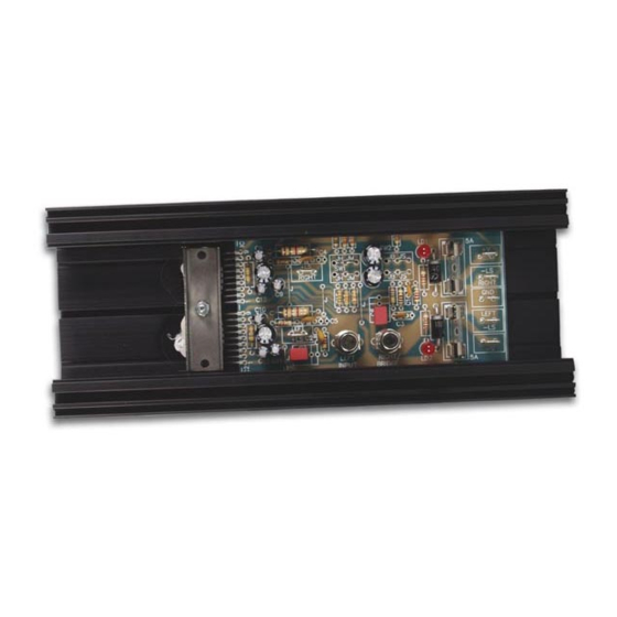
- Page 10 Power supply IC’s Slide the PCB into the largest slot of the heatsink and position it as shown in figure 4.0. Slide an insulation mica, provided with a drop of heat-conducting paste on both sides, under both IC's, see fig 5.0 Press the IC's against the heatsink.
- Page 11 Test 14. Test Connect a symmetrical supply (K4006 or a transfo 2 x 18VAC / 225VA) with + and - 28 VDC maximum to the GND (0V), -V and +V points. See figure 6.0. IMPORTANT: Never switch on the supply voltage and then connect to the amplifier! Switch on the supply voltage.
- Page 12 Use & connection 15. Use & connection NOTE : Carry out all connections by means of 1.5mm wire and the supplied flat connector bushes. Sol- der the wire to the connector bushes and slide the insulation over them. As a stereo amplifier: See Fig.
- Page 13 Use & connection As a mono-bridged amplifier: See Fig. 8.0 for the connection of the power supply and the speaker. Make sure that the impedance of the connected speaker is not less than 8 ohms. MONO BRIDGE : 100W POWER MIN.
- Page 14 Schematic diagram 16. Schematic diagram.
- Page 15 17. PCB...
- Page 16 VELLEMAN Components NV Legen Heirweg 33 9890 Gavere Belgium Europe www.velleman.be www.velleman-kit.com Modifications and typographical errors reserved © Velleman Components nv. H4004IP - 2004 - ED1 5 4 1 0 3 2 9 3 1 2 0 7 7...