Table of Contents
Advertisement
Quick Links
INSTALLATION, OPERATING AND SERVICING INSTRUCTION MANUAL
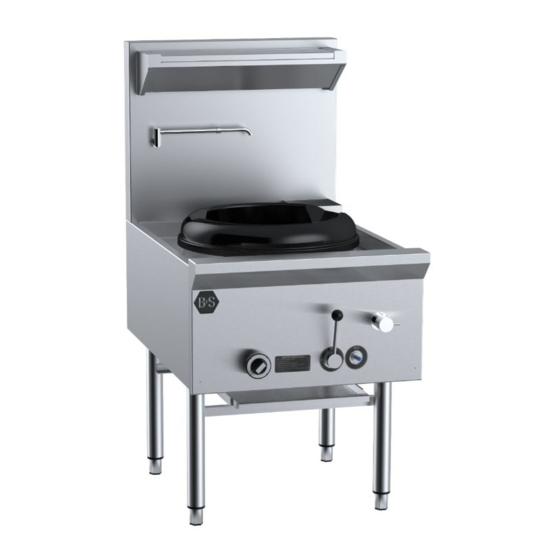
UFWWD, VUFWW & UFWWK Series Commercial Wok Boiling Table
Model No's.: (V)UFW–W(K)–D–1/2/3/4–CB/DB–SB1/2/3/4/5/6–LS
Tel: +61 3 9469 4754 Fax: +61 3 94694504 Web:
Please ensure this booklet is kept in a safe and prominent location for future reference.
The reproduction on or copying of any part of this booklet via any means is strictly forbidden unless agreed to in writing by the
manufacturer.
Owing to continual product development and improvements to its products, B&S Commercial Kitchens Pty Ltd reserves the right to
change the product specifications and design without prior notice.
Approval No: AGA 8749 G
B&S Commercial Kitchens Pty Ltd
57 Plateau Road Reservoir VIC 3073 AUSTRALIA
www.bscommercialkitchens.com
1
Advertisement
Table of Contents

Subscribe to Our Youtube Channel
Related Manuals for B+S UFWWD Series


Summary of Contents for B+S UFWWD Series
-
Page 1: Installation, Operating And Servicing Instruction Manual
INSTALLATION, OPERATING AND SERVICING INSTRUCTION MANUAL UFWWD, VUFWW & UFWWK Series Commercial Wok Boiling Table Model No’s.: (V)UFW–W(K)–D–1/2/3/4–CB/DB–SB1/2/3/4/5/6–LS Approval No: AGA 8749 G B&S Commercial Kitchens Pty Ltd 57 Plateau Road Reservoir VIC 3073 AUSTRALIA Tel: +61 3 9469 4754 Fax: +61 3 94694504 Web: www.bscommercialkitchens.com Please ensure this booklet is kept in a safe and prominent location for future reference. -
Page 2: Table Of Contents
Table of Contents INSTALLATION, OPERATING AND SERVICING INSTRUCTION MANUAL ........... 1 UFWWD, VUFWW & UFWWK Series Commercial Wok Boiling Table ............. 1 IMPORTANT WARNINGS ..........................6 Table 1: Nominal Terminal Input Rates & Injector Sizes ................4 Table 2: Standard Model ..........................4 Figure 1: Plumbing Connections ......................... - Page 3 Product Specifications & Introduction Appliance UFWW Series Commercial Wok Table Name: Also marketed under the brand name B&S Black, Verro & K plus Manufactured By: B&S Commercial Kitchens Pty Ltd Certificate Holder: 57 Plateau Road Reservoir Victoria 3073 Tel; + 61 3 9469 4754 Fax: +61 3 9469 4504 E-mail: info@bscommercialkitchens.com...
- Page 4 We are confident that you will be delighted with your B&S equipment, and that it will become the backbone of your kitchen. To ensure you receive the utmost benefit from your new B&S appliance, there are two important things you can do.
- Page 5 TABLE 3: Plumbing Connections Connection Position from Position from Position from Floor Rear of Appliance LHS/RHS edge (mm) (mm) of Appliance (mm) Water Inlet (W) ½” Copper 540(+/-5) 85 (+/-5) 120(+/-5) RHS Gas Inlet (G) ¾” male BSP 495(+/-5) 115 (+/-5) 115 (+/-5) RHS Water Outlet/Waste (D) 2”...
-
Page 6: Important Warnings
TABLE 5: Plumbing Connections Connection Position from Position from Position from Floor Rear of Appliance LHS/RHS edge (mm) (mm) of Appliance (mm) Water Inlet (W) ½” Copper 600(+/-5) 125 (+/-5) 100(+/-5) RHS Gas Inlet (G) ¾” male BSP 500(+/-5) 125 (+/-5) 100 (+/-5) RHS Water Outlet/Waste (D) 2”... -
Page 7: Installation Instructions
(a) Installed the appliance when gas is available at the time of installation; or (b) Makes gas available to the appliance if gas was not available at the time of installation As per AS/NZS5601.1, clause 6.11.3, the commissioning of this appliance shall take full account of special design features, the manufacturer’s instructions and the appliance safety requirements. -
Page 8: Gas Connection
Leave a clearance of at least 200mm between the appliance and any combustible surface. No combustible materials shall be located within 500mm of the wok table. Gas Connection The gas connection is male 3/4” BSP and is situated at the rear of the appliance below the main body frame. The number of gas inlets corresponds to the number of wok support rings the appliance is fitted with. -
Page 9: Chimney/Duck Bill - Where Fitted
D. If pilot light does not light, turn control knob to ‘OFF’ position, wait five minutes and repeat steps A to C. Note. If pilot flame is smaller than the parameters described in part A, check the pilot gas line (6mm stainless steel flexible tube) for any possible blockages/crimp age. -
Page 10: Operating Instructions
Operating Instructions WARNING • DO NOT spray aerosols in the vicinity of this appliance while it is in operation. • DO NOT store or use flammable liquids or items in the vicinity of this appliance. • Prior to lighting, smell area surrounding the appliance for gas (please note that as some gas types are heavier than air, we recommended the operator to also smell the floor around the appliance). -
Page 11: Lighting Instructions (Models Fitted With Combination Control)
Lighting Instructions (models fitted with combination control) Duck Bill Burner and Chimney Burner 1. Turn combination valve handle to the pilot position 2. Press the combination control valve handle firmly in from the centre of the valve and hold in while manually lighting the pilot. -
Page 12: Important Warning
adjustable flow rate automatically turns off with a non-concussive action after approximately 15 seconds. Closing time is not adjustable. IMPORTANT WARNING! IN THE EVENT OF FAILURE OF THE WOKSPOUT, WATER FLOW CAN BE CONTROLLED MANUALLY BY USING THE SPINDLE LOCATED ON FRONT PANEL (WHERE FITTED). WHERE NO SPINDLE FITTED, WATER SHOULD BE SWITCHED OFF FROM THE ISOLATION VALVE (WHICH IS RECOMMENDED TO BE FITTED WHEN ISTALLED) AND CONTACT AUTHORISED/ LICENSED SERVICE PERSONNEL. -
Page 13: Servicing Instructions
Servicing Instructions WARNING! • Servicing shall be carried out by authorised personnel only. Failure to do so will void the B&S warranty and may result in damage to equipment or injury to personnel. • Before commencing any disassembly/assembly of gas controls, please ensure the gas supply is turned off (isolated). -
Page 14: Adjustments
3. REASSEMBLE IN REVERSE ORDER. Adjustments Pilot 1. Remove front panel as described under GAINING ACCESS TO GAS CONTROL. 2. To increase gas pressure to pilot, turn adjustment screw located at the top right hand side of the flame failure devise anti-clockwise. - Page 15 Pilot established, main burner not lighting Contact manufacturer Faulty thermocouple Contact manufacturer Faulty flame failure control valve Telescopic laundry constantly running (on Change washers in tap assembly. water/deck cooled stock Warn tap washer pot tables) . Contact manufacturer or authorized service agent Short/Long Laundry...
- Page 16 B+S will endeavor to have a service technician on site for all warranty service requests within a 24 hour period or by end of next business day at the latest. All warranty requests must be in writing by either lodging a warranty request through B+S website or by emailing clientservices@bscommercialkitchens.com.
Need help?
Do you have a question about the UFWWD Series and is the answer not in the manual?
Questions and answers