
Subscribe to Our Youtube Channel
Related Manuals for Dahua DH-PFS4218-16GT-190


Summary of Contents for Dahua DH-PFS4218-16GT-190
- Page 1 Dahua 16/24-Port PoE Gigabit Managed Switch Quick Start Guide V1.0.3 ZHEJIANG DAHUA VISION TECHNOLOGY CO., LTD.
- Page 2 Cybersecurity Recommendations Mandatory actions to be taken towards cybersecurity 1. Change Passwords and Use Strong Passwords: The number one reason systems get “hacked” is due to having weak or default passwords. It is recommended to change default passwords immediately and choose a strong password whenever possible.
-
Page 3: Foreword
16/24-Port PoE Gigabit Managed Switch. Models Name Model 16-Port PoE Gigabit Managed Switch (190 W) DH-PFS4218-16GT-190 16-Port PoE Gigabit Managed Switch (240 W) DH-PFS4218-16GT-240 24-Port PoE Gigabit Managed Switch (240 W) DH-PFS4226-24GT-240 24-Port PoE Gigabit Managed Switch (360 W) - Page 4 Version Revision Content Release Time V1.0.3 Optimize description. August 2019 V1.0.2 Delete specifications June 2019 V1.0.0 First release. May 2018 Privacy Protection Notice As the device user or data controller, you might collect personal data of others' such as face, fingerprints, car plate number, Email address, phone number, GPS and so on.
-
Page 5: Important Safeguards And Warnings
Important Safeguards and Warnings The Guide helps you to use our product properly. To avoid danger and property damage, read the Guide carefully before using the product, and we highly recommend you to keep it well for future reference. Operating Requirements ... -
Page 6: Table Of Contents
Product Introduction ......................... 1 Product Features ........................1 Typical Application ........................1 2 Device Structure ..........................3 Front Panel..........................3 2.1.1 DH-PFS4218-16GT-190/240 ..................3 2.1.2 DH-PFS4226-24GT-240/360 ..................3 Rear Panel ..........................4 3 Installation ............................5 Installing the Device ......................... 5 Wiring ............................ -
Page 7: Overview
Overview Product Introduction The 16/24-Port Gigabit Managed PoE Switch is designed and developed for field tramission application of high definition video. The product is equipped with high performance switching engine and large buffer, which features low transmission delay and high reliability. Advantages of solid and sealed all-metal case design, low power consumption, fanless and efficient surface heat dissipation makes it work in the environment from -10℃... - Page 8 Figure 1-1 Networking Overview 2...
-
Page 9: Device Structure
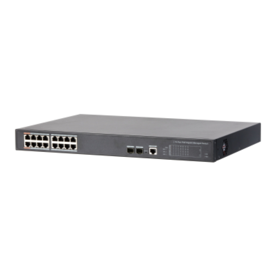
Device Structure Front Panel 2.1.1 DH-PFS4218-16GT-190/240 Figure 2-1 Front panel Table 2-1 Front panel description Name Description RJ-45 port Ethernet port, support 10/100/1000 M self-adaptive. SFP port Fiber port supports 1000 M. Reset button Long press the button for 5 s to reset the device and recover default configuration. -
Page 10: Rear Panel
Table 2-2 Front panel description Name Description RJ-45 port Ethernet port, support 10/100/1000M self-adaptive. SFP port Fiber port supports 1000M. Reset button Long press the button for 5 s to reset the device and recover default configuration. Console serial port Device debugging port. -
Page 11: Installation
Installation Installing the Device The device supports standard rack-mount. Install the rackmount kit on both sides of the switch. See Figure 3-1. Figure 3-1 Rack-mount Wiring 3.2.1 Ethernet Port Figure 3-2 Ethernet port pin No. 10/100/1000 Base-T Ethernet port adopts standard RJ-45 port. Equipped with self-adaptation function, it can be automatically configured to full duplex/half-duplex operation mode, and supports MDI/MDI-X self-recognition function of the cable, which means it can use cross-over cable or straight-through cable to connect terminal device to network device. -
Page 12: Console Port
The cable connection of RJ-45 connector conforms to the standard 568B (1-orange white, 2-orange, 3-green white, 4-blue, 5-blue white, 6-green, 7-brown white, 8-brown). 3.2.2 Console Port Figure 3-4 Console port See Figure 3-4 for console port. The switch console port and computer controlling 9-pin serial port are connected with RJ-45-DB9 cable. -
Page 13: Gnd
Figure 3-6 SFP module structure Figure 3-7 SFP module installation Installing SFP Port Step 1 It is recommended that before installing SFP module, you should wear antistatic gloves, and then wear antistatic wrist. Make sure that the antistatic gloves and the antistatic wrist are in good contact. - Page 14 enclosure GND with the GND screw. The other end of the GND cable should be reliably connected to the ground. The sectional area of the GND cable shall be more than 2.5mm² , and the GND resistance shall be less than 5Ω. Installation 8...
-
Page 15: Quick Operation
Quick Operation We will introduce VLAN configuration briefly in this section. See the corresponding command line manual for detailed configuration. First Login by Console Port Login by console port is the most basic way to log in the local interface, and it is also the method to configure other ways to log in the device. - Page 16 Step 7 The command line prompt (SWITCH#) is displayed after you press Enter key, as shown in the following. And you login the device successfully. +M25PXX : Init device with JEDEC ID 0xC22018. Luton10 board detected (VSC7428 Rev. D). RedBoot (tm) bootstrap and debug environment [ROMRAM] Non-certified release, version 1_31-4752 - built 17:29:35, Jul 29 2017 Copyright (C) 2000, 2001, 2002, 2003, 2004, 2005, 2006, 2007, 2008, 2009 Free Software Foundation, Inc.
-
Page 17: Restore To The Factory Default
Press ENTER to get started Username: admin Password: SWITCH# Enter the command, and you can configure the device and view the device ope rating status. You can enter ? anytime if you need help. Restore to the Factory Default You can log in the web interface of the device via the following IP address. Login the web interface of the device or login by console port with the user name and the password. - Page 18 Figure 4-2 VLAN networking Configuration Steps To configure the switch, do the following: Step 1 Create the VLAN. SWITCH #configure terminal SWITCH (config)#vlan 2 SWITCH (config-vlan)# exit SWITCH (config)#vlan 3 SWITCH (config-vlan)# exit Step 2 Allocate the ports into the VLAN. SWITCH(config)# interface GigabitEthernet 1/1 SWITCH (config-if)# switchport access vlan 2 SWITCH (config-if)# exit...
- Page 19 ZHEJIANG DAHUA VISION TECHNOLOGY CO., LTD. Address: No.1199, Bin'an Road, Binjiang District, Hangzhou, P.R. China Postcode: 310053 Tel: +86-571-87688883 Fax: +86-571-87688815 Email: overseas@dahuatech.com Website: www.dahuasecurity.com...
Need help?
Do you have a question about the DH-PFS4218-16GT-190 and is the answer not in the manual?
Questions and answers