Table of Contents
Advertisement
Quick Links
Instructions - Parts
HydroShield™ Automatic
HydroShield™
HydroShield™
Batch
Batch Waterborne
Batch
Waterborne Isolation
Waterborne
Air spray
spray system
system for
for use
use with
Air
Air
spray
system
for
use
fluids
fluids that
fluids
that meet
that
meet
meet at at at least
least
least one
permanent
permanent
permanent location.
location. Not
location.
Not approved
Not
For professional
professional use
use only.
only.
For
For
professional
use
only.
Important
Important Safety
Important
Safety Instructions
Safety
Read all warnings and instructions in this manual and in the spray
gun manual before using the equipment. Save
100 psi (0.7 MPa, 7.0 bar) Maximum
Fluid Working Pressure
100 psi (0.7 MPa, 7.0 bar) Maximum Air
Working Pressure
See page 5 for model information.
Automatic Air
Automatic
Isolation Systems
Isolation
with automatic
automatic electrostatic
electrostatic applicators
with
automatic
electrostatic
one of of of the
one
the conditions
the
conditions for
conditions
approved
approved for
for use
for
use in in in explosive
use
Instructions
Instructions
PROVEN QUALITY. LEADING TECHNOLOGY.
Air Spray
Spray
Air
Spray
Systems
Systems
applicators when
when spraying
applicators
when
for non
for
non- - - flammability
non
flammability
flammability listed
listed on
explosive atmospheres
explosive
atmospheres or or or hazardous
atmospheres
Save
Save these
these
these instructions.
instructions.
instructions.
spraying conductive,
conductive, waterborne
spraying
conductive,
listed
on page
on
page
page 4. 4. 4. To
To be
To
be used
be
hazardous (classified)
hazardous
(classified) locations.
(classified)
3A8493A
EN
waterborne
waterborne
used in in in a a a
used
locations.
locations.
Advertisement
Table of Contents
Troubleshooting

Related Manuals for Graco HydroShield WABL01


Summary of Contents for Graco HydroShield WABL01
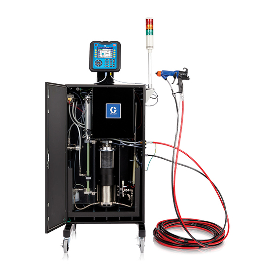
- Page 1 Instructions - Parts HydroShield™ Automatic Automatic Air Air Spray Spray HydroShield™ HydroShield™ Automatic Spray Batch Batch Batch Waterborne Waterborne Isolation Waterborne Isolation Systems Isolation Systems Systems 3A8493A Air spray spray system system for for use use with with automatic automatic electrostatic electrostatic applicators applicators when when spraying...
-
Page 2: Table Of Contents
Contents Contents Contents Related Manuals ..........3 Clean the Screen Surface......41 Update the System Software ......41 Isolation System Overview ........4 How the Isolation System Works ..... 4 Run Menus ............45 Spraying Waterborne Fluids Home Screen ..........45 Electrostatically ........ -
Page 3: Related Manuals
Description English English English 312782 Air Actuated Dispense Valve 312783 Color and Catalyst Change Valve Stacks 3A1244 Graco Control Architecture™ Module Programming 333012 Pro Xp™ Auto Waterborne Gun 332992 Pro Xpc™ Auto Gun 333266 Pro Xpc Electrostatic Controller 334452 ProBell ®... -
Page 4: Isolation System Overview
Isolation System Overview Isolation System System Overview Overview Isolation Isolation System Overview How the the Isolation Isolation System System Works Works Spraying Waterborne Waterborne Fluids Fluids Isolation System Works Spraying Spraying Waterborne Fluids Electrostatically Electrostatically Electrostatically When using a HydroShield Air Spray Waterborne Isolation System, the fluid supply remains grounded. -
Page 5: Models
Models Models Models Models Must purchase gun and hoses separately. Fluid Fluid Fluid Color Color Color Part Description Part Part Description Description regulator change regulator regulator change change � — WABL00 Isolation cabinet for automatic air spray. — — WABL01 Isolation cabinet for automatic air spray without fluid regulation. -
Page 6: Warnings
• Only use non-flammable solvents when flushing or cleaning equipment. • Only use the red-colored Graco electrically conductive gun air hose with this gun. Do not use black or gray-colored Graco air hoses. • Do not use pail liners unless they are conductive and grounded. - Page 7 Procedure . Procedure • Only use the red-colored Graco electrically conductive gun air hose with this gun. Do not use black or gray-colored Graco air hoses. • Do not splice hoses together. Install only one continuous Graco waterborne fluid hose between the isolated fluid supply and the spray gun.
- Page 8 Warnings WARNING WARNING WARNING EQUIPMENT EQUIPMENT EQUIPMENT MISUSE MISUSE HAZARD MISUSE HAZARD HAZARD Misuse can cause death or serious injury. • Do not operate the unit when fatigued or under the influence of drugs or alcohol. • Do not exceed the maximum working pressure or temperature rating of the lowest rated system component.
-
Page 9: Component Identification
Component Identification Component Identification Identification Component Component Identification Figure 1 Components of the Automatic Air Spray Isolation System. Item Item Item Description Description Description Item Item Item Description Description Description Air Inlet Fluid Pressure Regulator Electronics Panel Control Interface Color Change Module (on color change Ground Rod and Bleed Resistor enabled systems) Power Supply... -
Page 10: Typical Installation
Description Description Description AB † Bleed Type Air Valve Ground Lug AM † Main Air Supply Line Graco Waterborne Fluid Hose AS † Oil Separator Light Tower AV � Air Shut-off Valve Power Cord Isolation Cabinet † Required, not supplied. -
Page 11: Optional Multiple Gun Installation
Typical Installation Optional Multiple Multiple Gun Gun Installation Installation Optional Optional Multiple Installation fluid regulators (L) in the example, should be installed in an enclosure or location that prevents users from coming in contact with charged components any time electrostatics are in use. It is up to the person installing the system to accomplish this. - Page 12 Typical Installation Item Description Item Description Item Item Description Description Item Item Description Description Graco Waterborne Fluid Hose Isolated Region Fluid Pressure Regulator Fluid Manifold Electrostatic Applicator 3A8493A...
-
Page 13: Installation
Do not operate the gun unless ventilating air flow is Note: The Graco warranty and approvals are void if above the minimum required value. Provide fresh Note: Note:... -
Page 14: Mount The Cabinet
Installation Mount the the Cabinet Cabinet Mount Mount Cabinet Mount Mount on Mount on the the Wall Wall Wall Before mounting the isolation cabinet to the wall, make sure that the wall can support the weight of the system. See Technical Specifications, page 138 the weight. -
Page 15: Install The Light Tower
Installation Install the the Light Light Tower Tower Install Install Light Tower 4. Remove the feet (3a, 3b, 3c) from the frame. The system is equipped with a light tower which indicates how much paint is in the isolation fluid pump (K) as it fills and dispenses. -
Page 16: Grounding
Installation Grounding Grounding Grounding Power supply: • The power supply is grounded through the power cord to a grounded outlet. Spray gun: • Ground the gun according to the spray gun instruction manual. Waterborne fluid hose: • The hose must be properly grounded through the conductive layer. -
Page 17: Connect The Hoses
To reduce the risk of electric shock, install only one continuous Graco waterborne hose between the isolation cabinet and the gun. Do not splice hoses together. Always use a Graco waterborne fluid hose between the fluid outlet on the isolation cabinet and the gun fluid inlet. •... - Page 18 1. Blow the waterborne fluid hose out with air and flush with flushing fluid to remove contaminants. 2. Connect the Graco waterborne fluid hose to the gun as described in the spray gun manual. See the spray gun manual for hose information and dimensions.
- Page 19 Installation Connect Connect the Connect the Paint Paint Paint Trigger Trigger Trigger Input Input Input 8. Slide the nut (82a) onto the fluid hose, followed by the front ferrule (82b), and then the back ferrule (82c). The wider side of each ferrule (82b, The system relies on a pneumatic paint trigger signal 82c) faces the nut (82a).
- Page 20 Installation Connect the the Electrostatic Electrostatic Request Request Input Input Connect Connect Electrostatic Request Input 3. Feed these wires through the top right opening in the electronics control panel. The system needs to know when the use of 4. Connect the 24 VDC signal to A1+ and GND electrostatics is desired.
- Page 21 5. Connect terminal block 8 to GND. 8. Replace the isolation valve cover (99) and tighten Note the top and bottom screws (99a). When used with Graco electrostatic 9. Reinstall the electrostatic shield (12) inside the controllers, terminal block 7 signal cabinet.
- Page 22 Installation Connect Connect Connect the the Air Air Supply Supply Hose Supply Hose Hose to to to the the Cabinet Cabinet Cabinet Connect Connect the Connect the Fluid Fluid Supply Fluid Supply Hose Supply Hose to to to the Hose Cabinet Cabinet Cabinet...
-
Page 23: Connect The Can Cables
Installation Connect the the CAN CAN Cables Cables Connect Connect Cables 2. The system is equipped with another CAN cable (43) that is used to connect to the control interface: Connect the Control Area Network (CAN) cables to the control interface (42) so that the interface can On systems systems systems that... -
Page 24: Connect The Power Supply
Installation Connect the the Power Power Supply Supply Connect Connect Power Supply The power supply (47) with connector (X) is installed at the factory on the back of the isolation cabinet. Power cords with regional plugs are also supplied. Use a supplied power cord or purchase a regional plug separately. -
Page 25: Install The Optional System Stop Pneumatic Input Kit
Installation Install the the Optional Optional System System Stop Stop Install Install Optional System Stop 3. Mount the air pressure switch to the DIN rail (436) to the right of the other pressure switch(s), Pneumatic Input Input Kit Pneumatic Pneumatic Input as shown in the following figure. -
Page 26: Wire The System Stop Digital Input
Installation Wire the the System System Stop Stop Digital Digital Input Input Install the the Optional Optional System System Status Status Wire Wire System Stop Digital Input Install Install Optional System Status Output Output Output The System Stop Digital input provides a means to signal the HydroShield system to stop. -
Page 27: Wire The Low Paint Digital Output
Installation Wire the the Low Low Paint Paint Digital Digital Output Output Wire Wire Paint Digital Output 3. Switch the wires over to the new optocoupler ports: The Low Paint Digital output provides a means to Optocoupler Optocoupler Optocoupler Port Port Port Terminal... -
Page 28: Isolation System
Failure to follow this warning could cause fire, explosion, and electric shock and result in serious injury. Graco Part No. 241079 Megohmmeter (AB) is Figure 22 Check the Grounding of the Cabinet available as an accessory to check that the gun is properly grounded. -
Page 29: Operation
Operation Operation Operation Operation Operation Operation Operation Overview Overview Overview 2. Disable the electrostatic request signal to turn off electrostatics. 1. Plug in the system. The system 3. After the ground rod delay time elapses, the powers up and enters Off mode. See ground rod (N) inside the isolation cabinet lowers Connect the Power Supply, page and discharges the system. -
Page 30: Pressure Relief Procedure
Operation Pressure Relief Relief Procedure Procedure Pressure Pressure Relief Procedure 7. If the objective is to shut down and then service the system, relieve any residual pressure in the two flexible fluid lines between the inlet valves (J) and the isolation fluid pump (K). Note The contents of the isolation fluid pump This equipment stays pressurized until pressure is... -
Page 31: Flush The System (Systems Without Color Change)
Operation Flush the the System System (Systems (Systems without without Color Color Change) Change) Flush Flush System (Systems without Color Change) To flush systems that are color change enabled, 1. Release the gun trigger and turn off electrostatics follow the steps in Flush the System (Color Change by disabling the electrostatic request signal. -
Page 32: Flush The System (Color Change Enabled Systems)
Operation Flush the the System System (Color (Color Change Change Enabled Enabled Systems) Systems) Flush Flush System (Color Change Enabled Systems) To use use a a a purge purge profile: profile: purge profile: 1. If using purge profile 1-5, push the flashing Play button on the left side of the screen to run the purge sequence: To avoid fire and explosion, always ground... -
Page 33: Prime The Isolation System
Operation Spray with with the the Isolation Isolation System System Spray Spray with Isolation System 8. Release the gun trigger once the system has been sufficiently purged with air. 9. Follow the Pressure Relief Procedure, page Prime the the Isolation Isolation System System Prime... -
Page 34: Adjust The Gun Fluid Settings
Operation Adjust the the Gun Gun Fluid Fluid Settings Settings Adjust Adjust Fluid Settings 4. Turn on electrostatics by sending the system the ES request signal. This section only applies if the HydroShield is • The control interface displays the voltage equipped with an internal fluid pressure regulator. -
Page 35: Shutdown
Operation Shutdown Shutdown Shutdown To use use Preset Preset 1 1 1 through through 99: Preset through 1. Press the right arrow until Home appears 1. Discharge the system voltage. Follow the on the menu bar. Fluid Voltage Discharge and Grounding Procedure, page 2. -
Page 36: Control Interface
Control Interface Control Interface Interface Control Control Interface Soft Key Key Function Function Soft Soft Function Power Power Power The control interface displays graphical and text When the system is in Off mode, press information related to setup and spray operations. to activate the system. -
Page 37: Menu Bar
Control Interface Menu Bar Soft Key Key Icons Icons Menu Menu Soft Soft Icons The menu bar appears at the top of each screen. NOTICE NOTICE NOTICE To prevent damage to the soft key buttons, do not press the buttons with sharp objects such as pens, plastic cards, or fingernails. -
Page 38: Run Screens And Setup Screens
Control Interface Run Screens Screens and and Setup Setup Screens Screens Screens Setup Screens – Calibrate (See Calibrate Screens, page 57.) – System (See System Screen, page 65.) The control interface uses two sets of screens: – Pumps (See Pump Screens, page 54.) •... -
Page 39: Control Interface Setup And Maintenance
For instructions on how to use this file, serial number on the control interface. When Upload System Configuration, page downloading from multiple controllers, there is one sub-folder in the GRACO folder for each control For the location of the USB port on the control interface. module, see Connect the CAN Cables, page Retrieve the SETTINGS.TXT file after all system... -
Page 40: Download System Data
Windows ® Explorer. The following rules must be followed in order for the 6. Open the Graco folder. installation process to succeed. 7. Open the system folder. If downloading data • The file name must be DISPTEXT.TXT. from more than one system, there is more •... -
Page 41: Upload System Configuration
5. Open the system folder. If working with more than one system, there is more than one folder If you already have a Graco black software update within the Graco folder. Each folder is labeled token, you can use it to update the HydroShield with the corresponding serial number of the system software. - Page 42 Control Interface Setup and Maintenance 4. Save the GTI software update file to the Transfer the software to the system: \GRACO\SOFTWARE\ folder on the USB drive. 1. Navigate to Advanced Screen 4. See To automatically create the SOFTWARE folder Advanced Screen 4, page 56.
- Page 43 Control Interface Setup and Maintenance 6. When the process is ready to begin, the screen 3. Press the Power button to turn off the system. automatically transitions to the USB Software Note Update screen. If power is cycled while a token is •...
- Page 44 0.01.002 of the 17X093 software will be copied on how to update the software version of from the USB drive and will overwrite version Graco Control Architecture Modules. See 0.01.001 of 17X083 on the token. Related Manuals, page The progress of writing the software update to Note the token can take several minutes to complete.
-
Page 45: Run Menus
Run Menus Run Menus Menus Menus Home Home Home Screen Screen Screen The Home screen is the primary screen that the Soft Key Key Function Function Function Soft Soft operator uses while painting. When the system is Purge Purge Purge powered, it enters Off mode. - Page 46 Run Menus Home Screen Screen Without Without Color Color Change Change Home Screen Screen With With Color Color Change Change Enabled Enabled Home Home Screen Without Color Change Home Home Screen With Color Change Enabled Off Mode Mode Mode Standby Standby Standby Mode Mode...
- Page 47 Run Menus Key or or or Field Field Field Description Description Description Do Not Not Fill Fill Fill Activate Do Not Fill to prevent the isolation fluid pump from refilling when the trigger is released and the ES request signal is disabled. Do Not Fill is commonly used at the end of a paint job. Once the pump is empty, the system waits until another mode is selected.
- Page 48 Run Menus Key or or or Field Field Field Description Description Description Purge Purge Profile Purge Profile Profile Enter a purge profile number to purge the system automatically. (Available on color change enabled systems only.) The purge gun symbol indicates that the number is a purge profile number: To configure a purge sequence, see Purge Screens 1–5, page Gun Fluid...
- Page 49 Run Menus Home Home Home Screen Screen in in in Purge Screen Purge Mode Purge Mode Mode Home Home Home Screen Screen With Screen With With Color Color Change Color Change Change Enabled Enabled Enabled Manual Purge Purge Screen Screen Purge Profile Profile Screen Screen...
-
Page 50: Events Screen
Run Menus Events Screen Screen Events Events Screen Inputs are signals that the system acts on. When the status circle next to the input appears yellow, the sensor is activated. Use the Events screen to view the last 99 status messages generated by the isolation system. - Page 51 Run Menus Status Status Status Screen Screen 2 2 2 Screen Status Status Screen Status Screen Screen 3 3 3 Status screen 2 displays the current status of the Status screen 3 displays the inputs and outputs solenoids that drive activity for the color change related to automatic system operation.
-
Page 52: Setup Menus
Setup Menus Setup Menus Menus Setup Setup Menus Presets Presets Presets To unlock the Setup menus, press the Setup key Use this screen to preconfigure spray settings for If a password is configured, enter the password. different fluids, parts, and scenarios. (Default: 0000.) To configure a password, see For information about using Preset 0-99, see Advanced Screen 1, page... -
Page 53: Purge Screens 1-5
Setup Menus Purge Screens Screens 1–5 1–5 Purge Purge Screens 1–5 Use the Purge screens to configure up to 5 purge Purge: Purge: Purge: Assign a number to the purge profile. profiles. Customize each purge profile to best suit The purge profile number can be used: different fluids. -
Page 54: Pump Screens
Setup Menus Pump Screens Screens Pump Pump Screens Pump Screen Screen 2: 2: 2: Override Override Purge Purge Pump Pump Screen Override Purge Use the Pump screens to enter volume information about the isolation fluid pump and to manually purge the system in the event of a problem. -
Page 55: Advanced Screens
Setup Menus Advanced Screens Screens Advanced Advanced Screens Advanced Screen Screen 2 2 2 Advanced Advanced Screen To edit the information on a screen press the Enter Screen key Use this screen to select the pressure units for the system. To advance to the next Advanced screen, press the down arrow Advanced... - Page 56 Screen 4 4 4 Screen Use this screen to update the software part numbers and versions for the system components. Refer to this screen when contacting a Graco distributor for technical assistance. Press the magnifying glass to return to the previous screen.
-
Page 57: Calibrate Screens
Setup Menus Calibrate Screens Screens Calibrate Calibrate Screens Calibrate Calibrate Calibrate 1: 1: 1: Calibrate Calibrate Calibrate Pump Pump Pump Calibrate Calibrate the Calibrate the Pump Pump Pump Use the Calibrate 1 screen to calibrate the linear Before calibrating the isolation fluid pump, be sure position sensor in the isolation fluid pump. - Page 58 Setup Menus Calibrate Calibrate Calibrate 2: 2: 2: Fluid Fluid Fluid Calibrate Calibrate 3: 3: 3: Bleed Calibrate Bleed Bleed Resistor Resistor Resistor Use the Calibrate 2 screen to adjust the calibration Use the Calibrate 2 screen to adjust the value of the fluid.
-
Page 59: Maintenance Screens
Setup Menus Maintenance Screens Screens Maintenance Maintenance Screens Maintenance Maintenance Maintenance 1: 1: 1: Maintenance Maintenance Maintenance Due Maintenance Maintenance 2: 2: 2: Pump Maintenance Pump Stall Pump Stall Stall Test Test Test Use the Maintenance Due screen to set maintenance Use the Pump Stall Test screen to test the isolation reminders for system components. - Page 60 Setup Menus Pump Pump Pump Stall Stall Test Stall Test Test Procedure Procedure Procedure Maintenance Maintenance 3: 3: 3: Shuttle Maintenance Shuttle Valve Shuttle Valve Resets Valve Resets Resets and Test Test Test Before stall testing the isolation fluid pump, be sure that air and fluid are supplied to the system.
- Page 61 Setup Menus Maintenance Maintenance Maintenance 4: 4: 4: Fluid Fluid Fluid Valve Valve Valve Resets Resets Resets and and Test Test Test Maintenance Maintenance 5: 5: 5: Misc Maintenance Misc Misc Valve Valve Resets Valve Resets and Resets and Test Test Test View fluid valve actuation counts, reset those counts,...
- Page 62 Setup Menus Maintenance Maintenance Maintenance 6: 6: 6: Output Output Resets Output Resets Resets and and Test Test Test Maintenance Maintenance 7: 7: 7: Isolation Maintenance Isolation Isolation Valve Valve Maintenance Valve Maintenance Maintenance Use this screen to view system output counts, reset Use this screen to view isolation valve actuation those counts, and test the output.
- Page 63 Setup Menus Maintenance Maintenance Maintenance 8: 8: 8: Pump Pump Maintenance Pump Maintenance Maintenance Maintenance Maintenance 10: Maintenance 10: Color Color Color Change Change Valves Change Valves Valves Reset Reset and Reset and Test Test Test View information about maintaining the isolation fluid pump, including cycles and calendar days since the View the color change valve actuation counts, reset last stall test.
- Page 64 Setup Menus Maintenance Maintenance Maintenance 12: 12: Color Color Change Color Change Change Valves Valves Valves Maintenance Maintenance 14: Maintenance 14: Color Color Color Change Change Valves Change Valves Valves Reset Reset Reset and and Test Test Test Reset Reset and Reset and Test Test...
-
Page 65: System Screen
Setup Menus System Screen Screen System System Screen 1. The gun trigger is released and the electrostatic request signal is disabled. 2. Fill Start Delay (7) and Ground Rod Delay (5) begin at the same time. 3. After 5 seconds, the ground rod lowers and discharges the system. -
Page 66: Maintenance
Maintenance Maintenance Maintenance Maintenance Routine Maintenance Maintenance Routine Routine Maintenance Before performing any maintenance task, prepare the system for service. Follow the Prepare the System for Service, page Servicing this equipment requires access to parts which may cause electric shock or other serious injury if work is not performed properly. -
Page 67: Prepare The System For Service
Maintenance Maintenance Task Task Daily Weekly Maintenance Maintenance Task Daily Daily Weekly Weekly Perform a pump stall test. Follow the Pump Stall Test Procedure, page � Perform task any time fluid is seen at the weep holes on the isolation fluid pump, or any time the pump is serviced. -
Page 68: Replace The Wash Fluid
Maintenance Replace the the Wash Wash Fluid Fluid Replace Replace Wash Fluid Check the wash fluid bottle level. If the level changes, service the isolation valve seals. 1. Prepare the isolation system for service. Follow Prepare the Isolation System for Service, page 2. -
Page 69: Check And Lubricate The Ground Rod
Maintenance Check and and Lubricate Lubricate the the Ground Ground Rod Check the the Bleed Bleed Resistor Resistor Check Check Lubricate Ground Check Check Bleed Resistor 1. Check the ground rod (18): The bleed resistor (24) is used to help discharge the system voltage and to measure system performance. -
Page 70: Troubleshooting
Troubleshooting Troubleshooting Troubleshooting Troubleshooting To reduce the risk of an injury, follow the Installing and servicing this equipment requires Pressure Relief Procedure, page 30 whenever you access to parts which may cause an electric shock are instructed to relieve the pressure. or other serious injury if the work is not performed properly. - Page 71 Troubleshooting Problem Diagnosis Solution Problem Problem Diagnosis Diagnosis Solution Solution Spray The system thinks the gun is Make sure that both the paint The system does not fill. triggered or electrostatics are trigger signal and the ES request being requested. Either the PT signal are inactive.
- Page 72 Troubleshooting Problem Diagnosis Solution Problem Problem Diagnosis Diagnosis Solution Solution The system does not spray. 1. The system is not in Spray 1. Change to Spray mode. mode. 2. Give the system time to fill 2. The isolation fluid pump is before trying to paint.
- Page 73 Troubleshooting Problem Diagnosis Solution Problem Problem Diagnosis Diagnosis Solution Solution Low or no spraying voltage. • The ground rod (18) is not Voltage Loss raising. Troubleshooting, page • The isolation valve (227) is not raising. • The components or cabinet (9) is dirty.
-
Page 74: Led Diagnostic Information
Troubleshooting Problem Diagnosis Solution Problem Problem Diagnosis Diagnosis Solution Solution Other issues Paint build-up on the isolation 1. Follow the steps in Replace 1. Dirty wash fluid can no longer valve stem. clean properly. the Wash Fluid, page 2. The U-cup seals are not wiping 2. -
Page 75: Voltage Loss Troubleshooting
Troubleshooting Voltage Loss Loss Troubleshooting Troubleshooting Voltage Voltage Loss Troubleshooting 7. If the system is completely shorted out (0 kV) the fault may be with the mechanical operation of the isolation valve, grounding rod, or door Normal spraying voltage for a system is 45-55 switch. - Page 76 Troubleshooting Troubleshooting Troubleshooting Troubleshooting HydroShield HydroShield HydroShield Voltage Voltage Voltage Grounded components: • The cabinet. • All the parts mounted in the top half of the cabinet. • The top of the isolation valve. • The fluid inlet valve and hose. •...
-
Page 77: Valves
Troubleshooting Troubleshooting Color Color Change Change Solenoid Solenoid Valves Valves Troubleshooting Troubleshooting Color Change Solenoid Valves All color change solenoid valves may be exercised individually for diagnostic purposes through the control interface starting with Maintenance screen 10. Cause Solution Cause Cause Solution Solution... - Page 78 Troubleshooting Color Color Color Change Change Change Board Board Board NOTICE NOTICE NOTICE To avoid damaging the circuit boards, wear Part No. 112190 grounding strap on your wrist and ground appropriately. To avoid electrical component damage, remove all system power before plugging any connectors. Figure 32 Color Change Board 3A8493A...
- Page 79 Troubleshooting Table 5 5 5 Color Color Change Change Board Board Diagnostics Diagnostics Table Table Color Change Board Diagnostics Description Diagnosis Component Component or or or Component Description Description Diagnosis Diagnosis Indicator Indicator Indicator LED (green) Blinks (heartbeat) during normal operation. LED (green) Turns on when power is supplied to the board.
-
Page 80: Error Codes
User installed an incompatible USB Repeat the process with a compatible Advisory device in the Control USB device. WXUD USB Download Error Interface USB port. An unexpected WX00 Alarm Software Error software error has Call Graco technical support. occurred. 3A8493A... - Page 81 Error Codes Table 7 7 7 Communications Communications Errors Errors Table Table Communications Errors Type Name Description Code Code Code Type Type Name Name Description Description Solution Solution Solution • Verify the CAN connection on the system. See Connect the CAN Cables, page The control •...
- Page 82 Error Codes Code Type Name Description Solution Code Code Type Type Name Name Description Description Solution Solution • Verify CAN connection on the system. • Verify CAN connection on the The control solenoid controller board. interface has lost Communication Error communication with CAC2 Alarm...
- Page 83 F7P0 Alarm Invalid Air Flow detected when it should be off. • Check Air V/P. • Contact Graco technical support. The gun flush box was left open when the SGD1 Alarm Gun Flush Box Open Close the gun flush box.
- Page 84 Alarm V/P Cal Failed Air V/P calibration failed • Check V2P connections. for the Air V/P • Verify V2P operation • Contact Graco technical support. P513 Alarm V/P Cal Failed Fluid V/P Calibration failed • Check V2P connections. for the Fluid V/P •...
- Page 85 Error Codes Table 10 10 Maintenance Maintenance Events Events Table Table Maintenance Events Type Name Description Code Code Code Type Type Name Name Description Description Solution Solution Solution ENT1 Advisory Stall Test Pass System successfully Not applicable. completed a stall test. DF01 Advisory Stall Test Full Fail...
- Page 86 Follow token. the steps in Update the System Software, page WX00 Alarm Software Errors An unexpected Call Graco technical support. software error has occurred. WE00 Advisory Hydroshield detects Ground Rod Failure Check ground rod operation. electrostatic voltage when the ground rod is down.
- Page 87 Error Codes Table 12 12 USB USB Events Events Table Table Events Type Name Description Code Code Code Type Type Name Name Description Description Solution Solution Solution EAUX Advisory USB Busy USB drive is inserted, Not applicable. download is in progress.
- Page 88 Error Codes Table 13 13 Color Color Change Change Events Events Table Table Color Change Events Type Name Description Code Code Code Type Type Name Name Description Description Solution Solution Solution WSF0 Advisory Rejected Inlet Change User is unable to Changing of Color value is not change color/inlet allowed in Spray mode.
-
Page 89: Repair
Repair Repair Prepare the the Isolation Isolation System System for Repair Repair Prepare Prepare Isolation System Service Service Service Before servicing any component inside the isolation cabinet, perform the following steps: 1. Discharge voltage in the system. Follow all of the steps in the Fluid Voltage Discharge and Grounding Procedure, page... -
Page 90: Service The Isolation Valve
Repair Service the the Isolation Isolation Valve Valve Service Service Isolation Valve Reinstall Reinstall the Reinstall the Isolation Isolation Valve Isolation Valve Valve into into the into the Cabinet Cabinet Cabinet Use this procedure to reinstall the entire isolation Remove Remove Remove the the Isolation... - Page 91 Repair 2. Attach the isolation valve to the bottom of the 9. Before enclosing the isolation valve in the cabinet stand (9): isolation valve cover (99), ensure that the isolation valve shuttle (218) has a clear path to a. Insert the two screws (54) through flat travel up and down: washers (19), the base housing (201), and then insert into the bottom two holes of the...
- Page 92 Repair Adjust Adjust Adjust the the Isolation Isolation Valve Isolation Valve Valve Sensors Sensors Sensors Replace Replace an Replace an Isolation Isolation Isolation Valve Valve Sensor Valve Sensor Sensor When disassembling the isolation valve, you may The isolation valve sensor can be replaced while the have indicated the positions of the top and bottom isolation valve is in the cabinet or while it is removed valve sensors.
- Page 93 Repair Disassemble Disassemble Disassemble the the Isolation Isolation Valve Isolation Valve Valve 6. Replace the two shuttle bearings (223) in the shuttle housing (218). Components Components Components a. Remove the o-ring (231) on the underside of Use this procedure to disassemble the air cylinder the shuttle housing and pull the bearing out (227), block mount (224), connecting rods (225), through the top.
- Page 94 Repair Reassemble Reassemble the Reassemble the Isolation Isolation Isolation Valve Valve Valve 9. Reassemble the shuttle housing (218) assembly: Components Components Components a. Replace the wave washer (236). b. Slide the coupler (234) through the retaining Use this procedure to reassemble the air cylinder nut (235).
- Page 95 Repair Remove Remove the Remove the Isolation Isolation Valve Isolation Valve Stem Valve Stem Stem 10. Grip the flats of the connecting rod with an adjustable wrench. On the other side of the base housing (201), use an adjustable wrench to This procedure requires the sleeve tool (112) and tighten the screw to 120 in.
- Page 96 Repair Replace Replace Replace the the Isolation Isolation Valve Isolation Valve Stem Valve Stem Stem O O O - - - rings rings rings 4. To reassemble: a. Insert the spring (220) and the sleeve (221) Use this procedure to replace the three o-rings (219, (wider end first) into the sleeve tool (112).
- Page 97 Repair Service Service Service the the Bottom Bottom Bottom Piston Piston Housing Piston Housing Housing 6. Replace the piston seals: a. Place one U-cup (212) onto the piston (211). Use this procedure to replace the seals in the lower The U-cup must face the top (shaft of the piston housing.
- Page 98 Repair Service Service and Service and Reassemble Reassemble the Reassemble the Top Top Housing Housing Housing 11. To replace the seals in the top housing, see Service and Reassemble the Top Housing of the of of of the the Isolation Isolation Valve Isolation Valve...
- Page 99 Repair Reassemble Reassemble Reassemble the the Bottom Bottom Housing Bottom Housing of of of the Housing 4. Together, insert the piston tool (111) and piston (211) into the retainer (202) on the housing (201). Isolation Isolation Isolation Valve Valve Valve Push the piston (211) until the tool comes through the housing (201) and the piston (211) is in place.
-
Page 100: Service The Isolation Fluid Pump
Repair Service the the Isolation Isolation Fluid Fluid Pump Pump Service Service Isolation Fluid Pump Remove Remove Remove the the Isolation Isolation Fluid Isolation Fluid Pump Fluid Pump from Pump from from the 8. Remove the two fluid tubes from the fittings (327) at the base of the pump. - Page 101 Repair Reinstall Reinstall Reinstall the the Isolation Isolation Isolation Fluid Fluid Pump Fluid Pump Pump in in in the 4. Disassemble the fluid section of the pump: Cabinet Cabinet Cabinet a. Loosen the four tie rod screws (312) with a socket wrench.
- Page 102 Repair 5. Disassemble the air section of the pump: 7. To service the air piston (316): a. Loosen the four tie rod screws (312) with a a. Remove the o-ring (317) from the air piston socket wrench and remove. (316). b.
- Page 103 Repair Reassemble Reassemble the Reassemble the Isolation Isolation Isolation Fluid Fluid Fluid Pump Pump Pump 11. To remove and replace the wiper seal (306): a. Inside the middle housing (307) on the fluid 1. Lay the isolation fluid pump on its side. side, remove the wiper seal (306).
- Page 104 Repair Remove Remove the Remove the Fluid Fluid Fluid Regulator Regulator Regulator 14. With the air cylinder (319) up, place the air cover (320) onto the air cylinder (319). Make sure that o-ring (318) is in place on the cover. Grease the Remove the fluid regulator for service.
-
Page 105: Service The Electrical Controls
Repair Service the the Electrical Electrical Controls Controls Service Service Electrical Controls Replace Replace a a a kV Replace kV Board Board Board 1. Prepare the electrical controls for service. Follow Use the procedures in this section to service the steps in Prepare the Electrical Controls for components of the electrical controls as Service, page... - Page 106 Repair Replace Replace the Replace the Color Color Change Color Change Change Board Board Board Fuse Fuse Fuse 8. Perform the zero clear procedure on the V2P (415): The top of the V2P (415) contains 3 keys: Down arrow, Set (S), and Up arrow. Fuse Part Description...
- Page 107 Repair Electrical Electrical Electrical Schematics Schematics Schematics Figure 52 Electrical Schematic for 25E700 Electrical Control (equipped for fluid pressure regulator) 3A8493A...
- Page 108 Repair Figure 53 Electrical Schematic for 25E711 Electrical Control (NOT equipped for fluid regulator) 3A8493A...
-
Page 109: Pneumatic Connections
Repair Pneumatic Connections Connections Pneumatic Pneumatic Connections The numbers in the following figure represent Item Item Item Description Description Description Part Part Part point-to-point connections. For example, A4 5/32 inch tubing 598095 connects to A4. 3/8 inch tubing 054134 WABL02 & WABL03 Figure 54 Pneumatic Connections Table 14 14 Isolation... -
Page 110: Wiring Connections
Repair Wiring Connections Connections Wiring Wiring Connections The numbers in the following figure represent point-to-point connections. For example, C1 connects to C1. CAB LE CAB LE Figure 55 Wiring Connections 3A8493A... - Page 111 Repair Table 15 15 Wiring Wiring Connections Connections Table Table Wiring Connections ID ID ID Part Description Part Part Description Description 25R034 Bleed Resistor (24) ID ID ID Part Description Part Part Description Description 26C774 Power Supply (47) 17D923 Bulkhead Cable (59) Green/Yellow (20 in./50.8 cm) 121001 CAN Cable (43)
-
Page 112: Connections
Repair Color Change: Change: Pneumatic Pneumatic and and Wiring Wiring Connections Connections Color Color Change: Pneumatic Wiring Connections Figure 56 Color Change Module Wiring and Pneumatic Connections Table Table Table 16 16 Color Color Change Color Change Pneumatic Change Pneumatic Pneumatic Connections Connections Connections... -
Page 113: Parts
Parts Parts Parts Parts Isolation System System Isolation Isolation System Figure 57 Isolation Cabinet Isolation Cabinet Interior for a detailed view. * Fittings 79 and 128 are only present on systems with a fluid pressure regulator. 3A8493A... - Page 114 Parts Figure 58 Isolation Cabinet Interior Detail C1 C1 shows the parts that come with a standard system. Replace the C1 C1 parts with C2 C2 parts to add color change capability to a standard system. For more information, see Color Change Kit 26B415, page 128.
- Page 115 Parts Table 18 18 Isolation Isolation System System Table Table Isolation System Ref. Part Description Ref. Ref. Part Part Description Description 102023 SCREW, CAP, HEX HD Part Description Ref. Ref. Ref. Part Part Description Description (models WABL00 and WABL02) ------- ENCLOSURE, WATER- BORNE, BATCH, LP SCREW, CAP, HEX HD...
- Page 116 Parts Ref. Part Description Ref. Part Description Ref. Ref. Part Part Description Description Ref. Ref. Part Part Description Description 121001 103181 CABLE, CAN, FEMALE WASHER, LOCK EXT / FEMALE 1.0M (models 19Y391 FITTING, ELBOW, SWIVEL WABL00 and WABL01) (models WABL00 and 18C027 PLUG, HOLE, .687 INCH WABL02 only)
- Page 117 Parts Ref. Part Description Ref. Part Description Ref. Ref. Part Part Description Description Ref. Ref. Part Part Description Description 24W120 25R200 SENSOR, STROKE FLUID, CLEANSING, 1 POSITION GALLON (not shown) 19Y538 NUT, HEX, 5/16-24 16H930 WASHER, #10 FLAT SST (not shown) 19Y631 LABEL, SAFETY, WARNING,...
- Page 118 Parts Notes Notes Notes 3A8493A...
-
Page 119: 25N030 Isolation Valve Parts
Parts 25N030 Isolation Isolation Valve Valve Parts Parts 25N030 25N030 Isolation Valve Parts Figure 59 Isolation Valve 3A8493A... - Page 120 Parts Table 19 19 Isolation Isolation Valve Valve Table Table Isolation Valve Ref. Part Description Ref. Ref. Part Part Description Description 17Y486 SPRING, COMPR, 2.0 X OD 1.22 Part Description Ref. Ref. Ref. Part Part Description Description 221* 19A448 SLEEVE, ISOLATION VALVE ------- HOUSING, BASE, ISOLATION VALVE...
-
Page 121: 25N031 Isolation Fluid Pump Parts
Parts 25N031 Isolation Isolation Fluid Fluid Pump Pump Parts Parts 25N031 25N031 Isolation Fluid Pump Parts Figure 60 Isolation Fluid Pump 3A8493A... - Page 122 Parts Table 20 20 Isolation Isolation Fluid Fluid Pump Pump Table Table Isolation Fluid Pump Ref. Part Description Ref. Ref. Part Part Description Description 314* 15G747 MAGNET, LINEAR SENSOR Part Description Ref. Ref. Ref. Part Part Description Description 315* 160516 PACKING, O-RING, 214 19A952 PISTON, FLUID, ISOLATION...
-
Page 123: Electronic Control Parts
Parts Electronic Control Control Parts Parts Electronic Electronic Control Parts The following figure shows 25E700. Figure 61 Electronic Controls Note Systems without a fluid pressure regulator use electronics controls 25E711. Panel 25E711 does not have electro/pneumatic regulator 415, its associated hardware, or cables 446 and 449. 3A8493A... - Page 124 Parts Ref. Part Description Ref. Part Description Ref. Ref. Part Part Description Description Ref. Ref. Part Part Description Description ------- 19Y588 PANEL, WATERBORNE, ADAPTER, CABLE, CAN, IS TO PAINTED NON-IS ------- ------- COVER, ELECTRICAL, SCREW, MACH, PAN HD, #6-32 WATERBORNE 25D312 BOARD, CIRCUIT, GCA, CC, C06061...
-
Page 125: Repair Kits And Accessories
Repair Kits and Accessories Repair Kits Kits and and Accessories Accessories Repair Repair Kits Accessories Accessories Accessories Accessories Fluid Hoses Hoses Fluid Fluid Hoses 100 psi (0.7 MPa, 7.0 bar) Maximum Working Grounded Air Air Hoses Hoses for for Pro Pro Xp Xp Auto Auto... - Page 126 Software Upgrade Token 25R200 FLUID, CLEANSING, 1 GALLON This kit contains a Graco black software update token with the latest system software. A token is included when a replacement control interface is ordered. To use the token, see Update the System Software, page...
-
Page 127: Kit 26B400, Supply Pump
Repair Kits and Accessories Kit 26B400, 26B400, Supply Supply Pump Pump 26B400, Supply Pump This kit contains a Triton 1:1 pump to be assembled Ref. Ref. Ref. Part Part Part Description Description Description to the inlet side of the HydroShield system. 19Y578 BAR, MOUNTING 100731... -
Page 128: Color Change Kit 26B415
Repair Kits and Accessories Color Change Change Kit Kit 26B415 26B415 Color Color Change 26B415 Ref. Part Description Ref. Ref. Part Part Description Description ------- BAR, MOUNTING Parts included with Models WABL02 and WABL03 100731 WASHER, 3/8” and Kit 26B415. 100639 WASHER, LOCK, 3/8”... - Page 129 Repair Kits and Accessories Color Color Color Change Change Module Change Module Configuration Module Configuration Configuration Replace Replace the Replace the Color Color Change Color Change Change Board Board Board Configure each module according to its designated number, as follows: NOTICE NOTICE NOTICE...
- Page 130 Repair Kits and Accessories Figure 64 Control Module Repair (Non-IS Module Shown) Ref. Part Description Ref. Part Description Ref. Ref. Part Part Description Description Ref. Ref. Part Part Description Description 16P855 PANEL 113418 O-RING; buna-N BOARD, circuit; used with 100139 PLUG, pipe;...
- Page 131 Repair Kits and Accessories Non-IS Control Control Module Module Part Part Quantities Quantities Non-IS Non-IS Control Module Part Quantities Find your module kit number in the left column and the desired reference number in the top row to find the part quantity used in your control module kit. 6 6 6 - - - Position Position Position...
-
Page 132: Isolation Valve Kits
Repair Kits and Accessories Isolation Valve Valve Kits Kits Isolation Isolation Valve Kits Kit 26B401, 26B401, 26B401, Stem, Stem, Stem, Sleeve, Sleeve, Sleeve, Piston Piston Piston Kit 26B402, 26B402, Housing 26B402, Housing Assembly Housing Assembly Assembly Replacements Replacements Replacements Ref. Ref. - Page 133 Repair Kits and Accessories Kit 26B405, 26B405, Cap, 26B405, Cap, Piston Cap, Piston Retainer Piston Retainer Retainer Kit 26B410, 26B410, 26B410, Seal Seal Set Seal Set for for Service Service to to to Rebuild Service Rebuild Rebuild Bottom housing of the isolation valve. To replace, Be careful not to drop or scratch these parts when Service the Bottom Piston Housing, page handling.
-
Page 134: Isolation Fluid Pump Kits
Repair Kits and Accessories Isolation Fluid Fluid Pump Pump Kits Kits Isolation Isolation Fluid Pump Kits Kit 24A914, 24A914, 24A914, Bumpers Bumpers Bumpers Kit 26B423, 26B423, Fluid 26B423, Fluid Cylinder Fluid Cylinder Cylinder Part Description Ref. Ref. Ref. Part Part Description Description Ref. -
Page 135: Performance
Performance Performance Performance Performance The following figure shows how long it takes to fill the isolation fluid pump for a range of fluid viscosities. Dynamic Pressure at Fluid Inlet: 100 psi (.7 MPa, 6.9 bar) 80 psi (.6 MPa, 5.5 bar) 60 psi (.4 MPa, 4.1 bar) 40 psi (.3 MPa, 2.8 bar) Table... -
Page 136: Ignitability Of Coating Materials
Ignitability of Coating Materials Ignitability of of of Coating Coating Materials Materials Ignitability Ignitability Coating Materials Per EN 50059 From the Physikalisch-Technische Bundesanstalt, Braunschweig, Germany, June 26, 2019. General General General The fire and explosion protection of spraying systems can be facilitated considerably when processing coating materials with a low portion of solvents and a high flash point (generally water-based paints), provided that the spray cloud of the coating materials are considered to be non-ignitable. -
Page 137: Dimensions
Dimensions Dimensions Dimensions Dimensions Reference Reference Reference U.S. U.S. U.S. Metric Metric Metric Reference Reference Reference U.S. U.S. U.S. Metric Metric Metric 28.2 in. 71.6 cm 26.9 in. 68.3 cm 24.2 in. 61.5 cm 30.9 in. 78.5 cm 64.8 in. 164.6 cm 48.9 in. -
Page 138: Technical Specifications
Isolation System Air Inlet Fitting 1/2 npt(m) Isolation System Fluid Inlet Fitting 1/4 npsm(m) Isolation System Fluid Outlet 3/8 in. O.D. tube for Graco waterborne fluid hose Fitting Gun: Stainless Steel, PEEK, UHMWPE, Fluoroelastomer, Acetal, Nylon, Polyethylene, Tungsten Wire Wetted Parts... - Page 139 California Proposition 65 California Proposition Proposition 65 California California Proposition CALIFORNIA RESIDENTS RESIDENTS CALIFORNIA CALIFORNIA RESIDENTS WARNING: Cancer and reproductive harm — www.P65warnings.ca.gov. WARNING: WARNING: 3A8493A...
- Page 140 With the exception of any special, extended, or limited warranty published by Graco, Graco will, for a period of twelve months from the date of sale, repair or replace any part of the equipment determined by Graco to be defective.
Need help?
Do you have a question about the HydroShield WABL01 and is the answer not in the manual?
Questions and answers