Advertisement
INSTRUCTIONS-PARTS LIST
This manual contains IMPORTANT
WARNINGS
and
READ AND RETAIN FOR REFERENCE
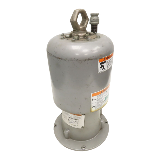
5.5 INCH
EFFECTIVE DIAMETER
SENATOR@ and QUIET SENATOR@
AIR MOTORS
psi (6.9 bar) MAXIMUM
Model
Series
4.75 in. Piston Stroke
Model
Series
Quiet SenatoP Air Motor
4.75 in Piston Stroke
Model
Series
8
in. Piston Stroke
INDEX
..........................................................
Warnings
Troubleshooting.
Models 217-540
...............................................
Models 220-571
Repair
Models 217-540 & 218-580
...............................................
Models 220-571
Parts Drawings
Lists
Models 217-540 8 218-580
...............................................
Model 220-571
.....................................................
Accessories
............................
Dimensional Drawings
....................................
Technical Data
.............................................
Warranty
GRACO INC. P.O. BOX I441 MINNEAPOLIS, MN 5-1444
INSTRUCTIONS
WORKING PRESSURE
C
A
A
.................................
.................................
..............................
Back Cover
.Back Cover
2
4
8
5
9
14
MODEL
16
Rev. F
SUPERSEDES E
SHOWN
....
.......
.... . .
.....
..
....
.....
Advertisement
Table of Contents

Subscribe to Our Youtube Channel
Related Manuals for Graco 217-540


Summary of Contents for Graco 217-540
- Page 1 Models 217-540 & 218-580 ..........Models 220-571 Parts Drawings Lists ......Models 217-540 8 218-580 ..........Model 220-571 ............. MODEL SHOWN Accessories ......Dimensional Drawings Back Cover ........Technical Data .Back Cover ..........Warranty GRACO INC. P.O. BOX I441 MINNEAPOLIS, MN 5-1444...
- Page 2 HIGH PRESSURE SPRAY .CAN CAUSE SERIOUS INJURY. U S E PROFESSIONAL ONLY. OBSERVE ALL WARNINGS. Read and understand all instruction manuals before operating equipment. HAZARD General Safety ALWAYS have the tip guard m on the spray gun while This equipment generates very high fluid pressure. Spray from spraying.
- Page 3 Do not use fluids or solvent8 which are not comoatible with the inner tube and cover of the hose. DO NOT expose Graco hose to temperature3 above 18ooF property damage. or below 40°F ~-40°C). ALL FLUID SPRAY HOSES MUST HAVE SPRING...
- Page 4 TROUBLESHOOTING MODELS 217-540 and 218- To restart a stalled motor, screw the lift ring (16) out of CHECK CHART 4-11 (See Fig the detent housing (36) and use a screwdriver t o push Stroke Ref. Fig. the valve housing down. See Figs 4-1.
- Page 5 REPAIRING MODELS Valve Repair Follow the Pressure Relief Procedure Warning on page NOTE: Refer to the Parts Drawing on page 12 for Steps 2 and 3. Remove the air inlet fitting (49). disconnect the ground wire, and remove the lift ring (16). NOTE: repair kit, part no.
- Page 6 Piston Repair 1. Remove the screws (7) and lockwashers and pull the cylinder Remove the trip rod bearing (47). using a 1 in. socket wrench. Remove the gasket (14). washer Pull the piston (2) and trip rod ( 5 0 ) up out of the base (48).
- Page 7 11. Install the air valve housing (29). washer (5) and trip Grease the piston O-ring and cylinder Place the cylinder upside down on a flat sur- rod nut Hold the flats of the valve housing face. Place the O-ring around the piston; the O-ring with a wrench.
- Page 8 INSTALLATION OF MODEL NOISE REDUCTION For the recommended air supply system installation see Mount the air motor resilient rubber pads, rather Instruction Manual 307-375. than sheet metal. These are additional recommendations for Maximum 3. Determine minimum air inlet pressure and pump cy- Noise Reduction.
- Page 9 REPAIRING MODEL 220-571 Valve Repair Follow the Pressure Relief Procedure Warning on page NOTE: Refer to the Parts Drawing on page 14 for when doing steps Disconnect the displacement pump. Remove the air inlet fitting disconnect the ground wire, and remove the lift ring NOTE: repair kit, part no.
- Page 10 Check the trip rod bearing (42). pressed into the air cylinder (41). and remove it if it's worn. Use special No. T38251, b a r i n g tool, Graco Pan t o press the bearing into place. Reassembly...
- Page 11 NOTE: See Figs 11-1 and 11-2 for Steps Grease and install the valve bushing (10). Grease and install the housing lockwasher and nut (7) on the trip rod (551. Adjust the housing nut (7) until 1 mm in.) of the rod projects, and then lock the nut in place.
-
Page 12: Parts Drawing
PARTS DRAWING Model 217-540, Series C Includes items 1-52 Model 218-580, Series A Includes items 1-52 MUST FACE UP... -
Page 13: How To Order Replacement Parts
Model 217-540, Series C Includes items 1-52 Model 218-580, Series A Includes items 1-52 REF PART DESCRIPTION REF PART DESCRIPTION NO. NO. NO. NO. detent spring RETAINER, spring GUIDE, SPRING, compression valve housing HUB, 100-101 air motor: 1 nDt(f) exhaust SHIELD. - Page 14 PARTS DRAWING Model 220-571. Series 1-64 Includes items...
-
Page 15: Parts List
PARTS LIST Quiet Senator Air Motor M o d e l 1-64 Includes items PART DESCRIPTION PART DESCRIPTION NO. NO. SEAL, plate, valve buna-n manifold . . . PLATE, valve GASKET, cellulose fiber . .. VALVE. director CAPSCREW, hex hd; M8 SPRING, compression 215251 AIR INLET FILTER ASSY. - Page 16 ALIGNMENT TOOL 168-513 AIR LINE FILTER 106-150 correctly aligning and spacing air manifolds. On Models 217-540 and 218-580 Micron element; 314 npt inlet and outlet AIR LINE LUBRICATOR 214849 bar) M A X I M U M WORKING PRESSURE Position tool on trip rod as shown.
-
Page 17: Technical Data
Graco distributor to the original purchaser for use. As purchaser's sole remedy for breach of this warranty, Graco will, for a period of twelve months from tha date of saie, repair or replace any part of the equipment proven defective.
Need help?
Do you have a question about the 217-540 and is the answer not in the manual?
Questions and answers