
Related Manuals for Advantech TPC-B610


Summary of Contents for Advantech TPC-B610
- Page 1 User Manual TPC-B610 電腦 Industrial Touch Panel Computer - Modular Computing Box with Intel® 10th Gen Core™ i CPU socket (LGA1200)
- Page 2 Note 2: “○” indicates that the percentage content of the restricted substance does not exceed the percentage of reference value of presence. 備考 3. 〝-〞係指該項限用物質為排除項目。 Note 3: The “−” indicates that the restricted substance corresponds to the exemption. TPC-B610 User Manual...
- Page 3 No part of this manual may be reproduced, copied, translated, or transmitted in any form or by any means without the prior written permission of Advantech Co., Ltd. The information provided in this manual is intended to be accurate and reliable.
- Page 4 Product Warranty (2 years) Advantech warrants the original purchaser that each of its products will be free from defects in materials and workmanship for two years from the date of purchase. This warranty does not apply to any products that have been repaired or altered by persons other than repair personnel authorized by Advantech, or products that have been subject to misuse, abuse, accident, or improper installation.
- Page 5 甲類警語 警告使用者:這是甲類資訊產品,在居住的環境中使用時,可能會造成射頻干擾,在 這種情況下,使用者會被要求採取某些適當對策。 Technical Support and Assistance Visit the Advantech website at www.advantech.com/support to obtain the latest product information. Contact your distributor, sales representative, or Advantech's customer service center for technical support if you need additional assistance. Please have the following information ready before calling: –...
- Page 6 Intel® Core™ i CPU Socket (LGA1200), PCIe x16, PCI TPC-B610W-A00A Intel® Core™ i CPU Socket (LGA1200), PCIe x16, PCIe x4, NVMe, RAID 0/1 *TPC-B610 is compatible with FPM-Display Module of sizes ranging from 15” to 23.8”. TPC-B610 User Manual...
- Page 7 M.2 (2242) SATA TPM 2.0 RAID 0, 1 For more information about the optional panel module, please find "FPM-Display Module" on Advantech’s website. Safety Instructions Read these safety instructions carefully. Retain this user manual for future reference. Disconnect the equipment from all power outlets before cleaning. Use only a damp cloth for cleaning.
- Page 8 In accordance with IEC 704-1:1982 specifications, the sound pressure level at the operator's position does not exceed 70 dB (A). DISCLAIMER: This set of instructions is given according to IEC 704-1. Advantech disclaims all responsibility for the accuracy of any statements contained herein.
-
Page 9: Table Of Contents
Safety and Environment..............3 1.2.4 OS support..................3 I/O Port Arrangement ................4 Figure 1.1 I/O Port Arrangement ..........4 Dimensions and Cutout................5 Figure 1.2 TPC-B610 Dimension..........5 Chapter System Setup ........7 Transport and Unpacking................8 2.1.1 Transport..................8 2.1.2... - Page 10 USB3.2 connector (CN7, CN20, CN21)........58 Table A.5: USB3.2 connector ............ 58 A.3.5 USB 2.0 connector (CN7) ............59 Table A.6: USB 2.0 connector ........... 59 A.3.6 COM1 RS232/422/485 connector (COM1)......... 59 A.3.7 COM2 RS232/422/485 connector (COM2)......... 59 TPC-B610 User Manual...
- Page 11 A.3.8 M.2 (B-Key) Slot (CN26 PCIe/USB/SATA) ......... 60 Table A.7: M.2 (B-Key) Slot (CN26 PCIe/USB/SATA)....60 A.3.9 M.2 (M-Key) Slot (CN17 NVMe/SATA Storage) ......61 Table A.8: M.2 (M-Key) Slot (CN17 NVMe/SATA Storage) ..61 TPC-B610 User Manual...
- Page 12 TPC-B610 User Manual...
-
Page 13: Chapter 1 General Information
Chapter General Information... -
Page 14: Introduction
10th Gen. Intel Core i Socket (LGA1200), a total of 64GB DDR4, com- prehensive I/Os including 6 x USBs, expansion via PCIe x16 and bountiful storage through M.2 SATA/NVME and 2 x 2.5" HDD/SSD slots. TPC-B610 allows easy pair- ing with panel modules ranging from 15" to 23.8" up to FHD resolutions. -
Page 15: System Hardware
1 x RS-232/422/485 (COM1) 5 x USB 3.2 (Gen1) 1 x USB 2.0 1 x DisplayPort 1.2 1 x Audio line out/ mic in Note! TPC-B610 supports only wide temperature (~85°C or wider) M.2 stor- age. 1.2.3 Safety and Environment 1.2.3.1 Safety FCC Class A ... -
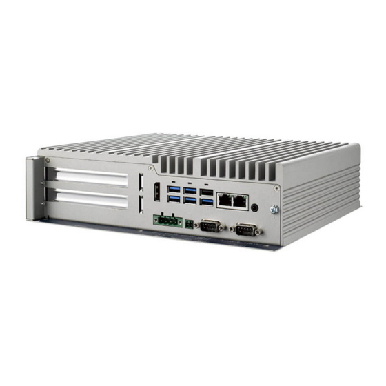
Page 16: I/O Port Arrangement
I/O Port Arrangement The arrangement of TPC-B610 I/O ports is shown in Figure 1.1. A. PCI expansion slot F. Remote Power B. 2.5” HDD/SSD slot G. RS-232, RS-232/422/485 C. DisplayPort H. RJ45 D. Power Receptor I. Audio line out/Mic in E. -
Page 17: Dimensions And Cutout
Dimensions and Cutout Weight (Net): 4.5 kg (9.92 lbs) Dimensions (L x W x H): 269 mm x 224 mm x 70 mm (10.6” x 8.8” x 2.8”) Figure 1.2 TPC-B610 Dimension TPC-B610 User Manual... - Page 18 TPC-B610 User Manual...
-
Page 19: Chapter 2 System Setup
Chapter System Setup... -
Page 20: Transport And Unpacking
TPC is switched on. 2.1.2 Unpacking Unpack the TPC-B610 package. Check the packing list at the beginning of this manual to make sure all items have been included. Connect the power connector (P/N: 1652006277-01) to the 24 VDC power lines. -
Page 21: Installation
Undo 4 screws and remove the top cover. Undo 3 screws on the bottom cover. Undo 3 screws on the I/O bracket. Figure 2.3 Removing Side Door Undo 3 screws on the side door. Undo 4 screws on the side door. TPC-B610 User Manual... - Page 22 M.2 (2280): Undo 1 screw (P/N: 19350304A0), affix the thermal pad (P/N: 1990037589N000) and reassemble the M.2 SSD. Note! Thermal pad and memory thermal cover must be completely covered and secured. TPC-B610 supports only wide temperature (~85°C or wider) M.2 stor- age. TPC-B610 User Manual...
-
Page 23: Memory (Channel 2)/Mpcie/M.2 (3052/2242)
Memory (Channel 2)/mPCIe/M.2 (3052/2242) Figure 2.5 Removing Bottom Cover Undo 9 screws on the bottom cover. Remove the bottom cover. Undo 1 screw on the thermal bracket. Remove the thermal bracket. Figure 2.6 Top View - Memory (Channel 2)/mPCIe/M.2 (3052/2242) TPC-B610 User Manual... -
Page 24: Hdd/Ssd (2.5")/Pci Expansion/Idoor Module
PCIe slots by using an extra adapter "PCM-28P1AD". *Please find "Advantech iDoor Module" on Advantech's official website for more infor- mation about the iDoor module choices, and check with your local sales support for compatibility confirmation. -
Page 25: Panel Module
TPC-B610. For more information about the FPM-Display Module, please check Advantech’s official website of “FPM-Display Module”. Use the 5 screws (1930000881) included in the accessory kit to attach the TPC-B610 to the optional panel module via the board-to-board connector. - Page 26 Please make sure the Boss on the left sides on the back of the optional panel should be installed in the holes with a signal of one dot aside, as marked in yellow in the picture below, so to be successfully paired with TPC-B610. TPC-B610 User Manual...
-
Page 27: Panel Mounting
Panel Mounting This chapter describes the panel mounting methods. It is applicable to TPC-B610 when an optional FPM-Display Module is paired with TPC-B610. For more informa- tion about the FPM-Display Module, please check Advantech’s official website of “FPM-Display Module”. Position the system (TPC-B610 + FPM-Display Module) against the wall Figure 2.12 Panel Mounting –... - Page 28 The meanings of the varied colors of the LED indicator on the optional FPM-Display module are as follows: ACPI Sleep States Definition Color of LED Indicator Normal Powered-On State Blue Suspend to RAM Orange Suspend to Disk Orange Soft Off Orange TPC-B610 User Manual...
-
Page 29: Vesa Mounting
VESA Mounting TPC-B610 supports VESA 100x100 standard. M4 x 10 screws are recommended for VESA mounting. Please find below the picture of TPC-B610 when combined with optional FPM-Dis- play Module. Figure 2.15 VESA Mounting TPC-B610 User Manual... - Page 30 TPC-B610 User Manual...
-
Page 31: Chapter 3 Bios Setup
Chapter BIOS Setup... -
Page 32: Introduction
The Setup Utility uses a number of menus for making changes and turning the specific features on or off. This chapter describes the basic navigation of the TPC-B610 setup screens. Figure 3.1 Main setup screen AMI’s BIOS ROM has a built-in Setup program that allows users to modify the basic... -
Page 33: Entering Bios Setup
System Date using the <Arrow> keys. Enter new values through the keyboard. Press the <Tab> key or the <Arrow> keys to move between fields. The date must be entered in MM/DD/YY format. The time must be entered in HH:MM:SS format. TPC-B610 User Manual... -
Page 34: Advanced Bios Features Setup
3.2.2 Advanced BIOS Features Setup Select the Advanced tab from the TPC-B610 setup screen to enter the Advanced BIOS setup screen. You can select any of the items in the left frame of the screen, such as CPU configuration, to go to the sub menu for that item. You can display an Advanced BIOS Setup option by highlighting it using the <Arrow>... - Page 35 3.2.2.1 Platform Misc Configuration Figure 3.4 Platform Misc Configuration Platform Misc Configuration – Native PCIE Enable PCI Express Native Support Enable/Disable. TPC-B610 User Manual...
- Page 36 "Enable or Disable" utilization of additional hardware capabilities provided by Intel Trusted Execution Technology. Changes require a full power cycle to take effect. Rest AUX Content Reset TPM AUX content. TXT may not be functional after AUX content gets reset. TPC-B610 User Manual...
- Page 37 3.2.2.3 Power & Performance Figure 3.6 Power & Performance Figure 3.7 CPU Power Management Control Boot Performance Select the performance state that the BIOS will set before OS handoff. TPC-B610 User Manual...
- Page 38 Allows more than two frequency ranges to be supported. Turbo Mode Turbo mode. C states Intel C states setting for power saving. 3.2.2.4 PCH-FW Configuration Figure 3.8 PCH-FW Configuration PCH-FW Version PCH-FW page shows Intel ME FW information. TPC-B610 User Manual...
- Page 39 3.2.2.5 Trusted Computing Figure 3.9 TPM Settings TPM Support “Enable or Disable” TPM Support. TPC-B610 User Manual...
- Page 40 OS. ACPI Sleep State Auto or S1 only or S3 only ACPI Sleep State. Lock Legacy Resources Enable or Disable Lock Legacy Resources. S3 Video Repost Enable or Disable S3 Video Repost. TPC-B610 User Manual...
- Page 41 3.2.2.7 SMART Settings Figure 3.11 SMART Settings SMART Self Test Enable or Disable SMART Self Test on all HDDs during POST. TPC-B610 User Manual...
- Page 42 3.2.2.8 Super I/O Configuration Figure 3.12 Super IO Configuration Figure 3.13 Serial Port 1 Configuration TPC-B610 User Manual...
- Page 43 Change Settings – This item allows users to Change Settings of Serial Ports. The default setting is Auto. – Device Mode This item allows users to set the mode of serial port. The default setting is RS-232. TPC-B610 User Manual...
- Page 44 Figure 3.15 PC Health Status 3.2.2.10 S5 RTC Wake Settings Figure 3.16 S5 RTC Wake Settings Wake system with Fixed Time To Enable or Disable System wake on alarm event. The system will wake on the hr:min:sec as specified. TPC-B610 User Manual...
- Page 45 Console Redirection Enable or Disable Legacy Console Redirection – Legacy Console Redirection Settings Legacy Console Redirection Settings Serial Port for Out-of-Band Management/ Windows Emergency Manage- ment services (EMS) – Console Redirection Console Redirection Enable or Disable TPC-B610 User Manual...
- Page 46 3.2.2.12 Intel TXT Information Figure 3.18 Intel TXT Information 3.2.2.13 USB Configuration Figure 3.19 USB Configuration TPC-B610 User Manual...
- Page 47 Controller. Auto uses default value: for a Root port it is 100 ms, for a Hub port the delay is take from Hub descriptor. 3.2.2.14 USB Network Stack Configuration Figure 3.20 Network Stack Network Stack "Enable or Disable" UEFI Network Stack. TPC-B610 User Manual...
- Page 48 Controls the execution of UEFI and Legacy Storage OpROM. – Video Controls the execution of UEFI and Legacy Video OpROM. – Other PCI devices Determines OpROM execution policy for devices other than Network, Stor- age, or Video. TPC-B610 User Manual...
- Page 49 Controls the execution of UEFI and Legacy Storage OpROM. – Video Controls the execution of UEFI and Legacy Video OpROM. – Other PCI devices Determines OpROM execution policy for devices other than Network, Stor- age, or Video. 3.2.2.16 NVMe Configuration Figure 3.22 NVMe Configuration TPC-B610 User Manual...
- Page 50 3.2.3 Chipset Configuration Figure 3.23 Chipset This page provides information of the chipset on TPC-B610. 3.2.3.1 System Agent (SA) Configuration Figure 3.24 System Agent (SA) Configuration TPC-B610 User Manual...
- Page 51 3.2.3.2 Memory Configuration Figure 3.25 Memory Configuration Maximum Memory Frequency Maximum memory frequency selections in Mhz. 3.2.3.3 Graphics Configuration Figure 3.26 Graphics Configuration TPC-B610 User Manual...
- Page 52 Figure 3.27 Primary Display Settings Figure 3.28 Internal Graphics Settings Primary Display Set Primary Display to "Auto", "IGFX", "PEG", "PCI", or "SG". Primary Display Select PEG0/PEG1/PEG2/PEG3 graphics device should be Primary PEG. TPC-B610 User Manual...
- Page 53 Enable or disable the root port Max Link speed Configure PEG 0:1:0 max speed PEG Port Feature Configuration – Detect Non-Compliance Device Detects non-compliance PCI Express device in PEG. If enabled, it will take more time during POST phase. TPC-B610 User Manual...
- Page 54 Enable or Disable PCIE to wake the system from S5. PowerOn by Modem "Enable and Disable" PowerOn by Modem Restore AC Power Loss Power off or Power on or Last State to restore AC Power Loss TPC-B610 User Manual...
- Page 55 Select "Auto, Gen1, Gen2, Gen3" for PCIe Speed Note! Please find below the corresponding board connectors for PCIe Root Port. PCI Express Root Port MotherBoard Connector Note mPCIe slot (CN 16) 22-25 M.2 key-M (2280) (CN15) Only for TPC-B610W-A00A TPC-B610 User Manual...
- Page 56 Hot Plug Enable or Disable SATA Hot-Plug Spin up Device Enable or Disable spin up device SATA Device Type| To identify the SATA that is connected to a Solid State or Hard Disk Drive. TPC-B610 User Manual...
- Page 57 3.2.3.8 USB Configuration Figure 3.33 USB Configuration XHCI Compliance mode Option to "Enable or Disable" XHCI compliance mode. Default is to disable com- pliance mode. TPC-B610 User Manual...
- Page 58 "Enable or Disable" the PCH BIOS Lock Enable feature. Required to be enabled to ensure SMM protection of flash. Force unlock on all GPIO pads If Enabled, BIOS will force all GPIO pads to be in an unlocked state. TPC-B610 User Manual...
- Page 59 3.2.3.10 HD Audio Configuration Figure 3.35 HD Audio Configuration HD Audio Control detection of the HD-Audio device. Disable = HDA will be unconditionally disabled Enable=HDA will be unconditionally enabled TPC-B610 User Manual...
- Page 60 3.2.4 Security Select Security Setup from the TPC-B610 Setup main BIOS setup menu. All Security Setup options, such as password protection is described in this section. To access the sub menu for the following items, select the item and press <Enter>.
- Page 61 3.2.4.1 Secure boot Figure 3.36 Secure Boot TPC-B610 User Manual...
- Page 62 "On or Off" power-on state for the NumLock. Quiet Boot Enable or Disable Quiet Boot option. Boot Option Priorities Sets the boot order. Hard Drive BBS Priorities Sets the order of the legacy devices on this group. TPC-B610 User Manual...
- Page 63 1. Select Exit Discarding Changes from the Exit menu and press <Enter>. The following message appears: Quit without saving? [Yes] [No] 2. Select Yes to discard changes and exit. Discard Changes Select Discard Changes from the Exit menu and press <Enter>. TPC-B610 User Manual...
- Page 64 TPC-B610 User Manual...
- Page 65 Appendix MB I/O Connector...
- Page 66 Jumper, Dip switch and Connector location A.1.1 Mother Board Placement Figure A.1 Top View of Motherboard Figure A.2 Bottom View of Motherboard TPC-B610 User Manual...
- Page 67 Jumper setting and Description A.2.1 CMOS Clear Function (JCMOS1) Table A.1: CMOS Clear Function Description This jumper is used to select CMOS Clear Enable/Disable Default (1-2) (2-3) Enable (Clear CMOS) (1-2) Disable (1-2) Disable (2-3) Enable (Clear CMOS) TPC-B610 User Manual...
- Page 68 SIM card data system ground SIM card 5V power PCIE_- device pcie clock SIM_VCC input CLKREQ# request output 1.5V 1.5V power input floating system ground floating 3.3V standby power host wake up trig- 3.3V PCIE_WAKE# input ger output TPC-B610 User Manual...
- Page 69 A.3.2 Power-in connector Table A.3: Power-in connector Description 24Vdc 24Vdc TPC-B610 User Manual...
- Page 70 Description VBUS 5V power output USB2_D- USB2.0 data negative USB2_D+ USB2.0 data positive system ground USB3_RX- USB3.0 data receive negative USB3_RX+ USB3.0 data receive positive system ground USB3_TX- USB3.0 data transmit negative USB3_TX+ USB3.0 data transmit positive TPC-B610 User Manual...
- Page 71 DTR# ready positive system ground system ground system ground DSR# data set ready RTS# request to send CTS# clear to send ring indicator Legend: “-” = “no data” TPC-B610 User Manual...
- Page 72 Connector key B Connector key B Connector key B Connector key B Connector key B Connector key B GPIO_9/DAS/DSS (I/O)/ LED_1# (I) (0/ USB_D- 3.3V) W_DISABLE1# (O) (0/1.8V/3.3V) USB_D+ FULL_CARD_POWER_OFF# (O) (0/ 18.V or 3.3V) 3.3V 3.3V CONFIG_3 TPC-B610 User Manual...
- Page 73 Connector key M Connector key M Connector key M Connector key M Connector key M Connector key M REFCLKp PEWAKE# (I/O) (0/1.8V/3.3V) or NC REFCLKn CLKREQ# (I/O) (0/1.8V/3.3V) or NC PERST# (O) (0/1.8V/3.3V) or NC PETp0/SATA-A+ PETn0/SATA-A- TPC-B610 User Manual...
- Page 74 PLA_S3# (I) (0/1.8V/3.3V) or NC PERn1 PETp2 PETn2 VIO 1.8V or NC PERp2 3.3V PERn2 3.3V 3.3V PETp3 3.3V PETn3 DAS/DSS (I/O)/ LED_1# (I) (0/3.3V) PLN# (O)(0/1.8/3.3V) or NC PERp3 PWRDIS (O)(0/1.8/3.3V) or NC PERn3 3.3V 3.3V TPC-B610 User Manual...
- Page 75 TPC-B610 User Manual...
- Page 76 No part of this publication may be reproduced in any form or by any means, electronic, photocopying, recording or otherwise, without prior written permis- sion of the publisher. All brand and product names are trademarks or registered trademarks of their respective companies. © Advantech Co., Ltd. 2021...
Need help?
Do you have a question about the TPC-B610 and is the answer not in the manual?
Questions and answers