
Related Manuals for Advantech TPC-B300 Series


Summary of Contents for Advantech TPC-B300 Series
- Page 1 User Manual TPC-B300 Series TPC-B300-J20A TPC-B300-E20A Industrial Modular Touch Panel Computer with Intel® Atom™/ Celeron® Processor...
- Page 2 Note 2:“ ○ ” indicates that the percentage content of the restricted substance does not exceed the percentage of reference value of presence. 備考 3.“ - ” 係指該項限用物質為排除項目。 Note 3:The “ ? ” indicates that the restricted substance corresponds to the exemption. TPC-B300 Series User Manual...
- Page 3 No part of this manual may be reproduced, copied, translated or transmitted in any form or by any means without the prior written permission of Advantech Co., Ltd. Information provided in this manual is intended to be accurate and reliable. How- ever, Advantech Co., Ltd.
- Page 4 Because of Advantech’s high quality-control standards and rigorous testing, most of our customers never need to use our repair service. If an Advantech product is defec- tive, it will be repaired or replaced at no charge during the warranty period. For out- of-warranty repairs, you will be billed according to the cost of replacement materials, service time and freight.
- Page 5 警告使用者:這是甲類資訊產品,在居住的環境中使用時,可能會造成射頻干擾,在 這種情況下,使用者會被要求採取某些適當對策。 Technical Support and Assistance Visit the Advantech web site at www.advantech.com/support where you can find the latest information about the product. Contact your distributor, sales representative, or Advantech's customer service center for technical support if you need additional assistance. Please have the following information ready before you call: –...
- Page 6 The sound pressure level at the operator's position according to IEC 704-1:1982 is no more than 70 dB (A). DISCLAIMER: This set of instructions is given according to IEC 704-1. Advantech disclaims all responsibility for the accuracy of any statements contained herein.
-
Page 7: Table Of Contents
Entering Setup ..................22 3.1.1 Main Setup.................. 22 3.1.2 Advanced BIOS Features Setup..........23 3.1.3 Chipset Configuration ..............32 3.1.4 Security ..................32 3.1.5 Boot..................... 33 3.1.6 Save & Exit ................. 34 3.1.7 Wake up on LAN................. 35 TPC-B300 Series User Manual... - Page 8 LAN Driver Installation ................57 Intel® Trusted Execution Engine Driver Installation........ 59 Advantech EC Driver Installation ............62 Advantech EC Brightness Control Tool Installation ........ 64 Advantech EC Watchdog Timer Driver Installation......... 66 Advantech LMsensor Driver Installation ..........69 TPC-B300 Series User Manual...
-
Page 9: Chapter 1 General Information
Chapter General Information... -
Page 10: Introduction
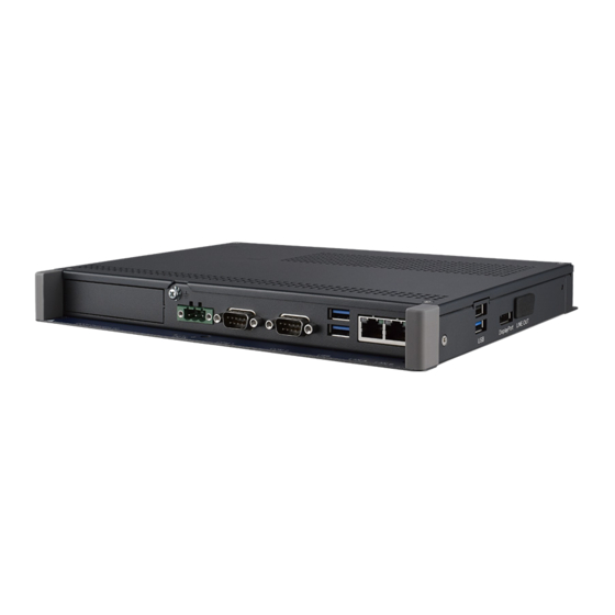
USB 3.1 x 3 – USB 2.0 x 1 – Audio line out x 1 – Display port 1.4 out x 1 – 2.5Gb LAN x 2 (2 x Intel® I226) 1.2.2 O/S support Windows 10 IoT Enterprise LTSC TPC-B300 Series User Manual... -
Page 11: Certification And Environment
5-Wire resistive PCAP PCAP 5-Wire resistive Light Transmission Above 75% 90% ± 3% 90% ± 3% Above 75% Touchscreen Anti-Glare Treatment Built-In iKey WiFi/NFC Support Expandability Optional (Please contact Advantech for more information.) on Front Panel TPC-B300 Series User Manual... -
Page 12: Power
PCAP Light Transmission 90% ± 3% Touchscreen Anti-Glare Treatment Built-In iKey WiFi/NFC Support Expandibility Optional (Please contact Advantech for more information.) on Front Panel Power Input Voltage: 24V +/- 20% Typical: 24 V @ 2.5 Amp I/O Port Arrangement The arrangement of the I/O ports is shown in Figure 1.1... -
Page 13: Panel Mounting
Hook the clamps into the holes and fasten the screws Torque: 2 kgf-cm These screws will push the mounting panel and secure the unit. Figure 1.2 Panel mounting Dimensions and Cutout Unit: mm TPC-B300 Series User Manual... -
Page 14: Led Indicators On Optional Fpm-Display Module
LED indicators on optional FPM-Display module Table 1.3: LED Indicators Indicator Status (Default ErP Enable) Status (ErP Disable) Green Normal Powered-On State Normal Powered-On State Orange Standby No Light TPC-B300 Series User Manual... -
Page 15: Chapter 2 System Setup
Chapter System Setup... -
Page 16: Transport And Unpacking
12 hours must be allowed to make sure the TPC is completely dry before the TPC is switched on. System Setup Note! If you purchase the Computing Box (TPC-B200) & Panel (FPM-Display) separately, please simply use the five screws of 1930001361 to connect the Computer Box and Panel. TPC-B300 Series User Manual... - Page 17 Unscrew the cover of box module and remove HDD bracket. Figure 2.1 Install SSD - 1 Figure 2.2 Install SSD - 2 Fasten SSD with the disk tray with the SSD screws. Figure 2.3 Install SSD – 2 TPC-B300 Series User Manual...
- Page 18 Figure 2.4 Power connector and pin assignment Plug the power wire into the system power receptor. Figure 2.5 Power Receptor & Button Pin Assignment Attach power to the system. Calibrate the touchscreen. (only applicable to 12.1”) TPC-B300 Series User Manual...
-
Page 19: Driver Installation
With administrator-level privileges, run the installer for the Advantech watchdog driver. Below is an example of the Advantech watchdog driver setup. To stop the setup pro- cess at any time, click the “Cancel” button on the pop-up screen. The setup program will stop the procedure automatically. - Page 20 Wait until the Advantech Watchdog Driver Setup Wizard has completed the installation. Click the “Install” button to continue the installation of the Advantech watchdog driver software. TPC-B300 Series User Manual...
-
Page 21: Panel Mounting
Click the “Restart” or “Close” button on the Advantech Watchdog Driver Setup Wizard pop-up screen to complete the setup. Panel Mounting Position the TPC against the panel. TPC-B300 Series User Manual... - Page 22 Insert the clamps into the side of the TPC. Secure the clamp to the panel using the included screws. TPC-B300 Series User Manual...
-
Page 23: Cabinet Installation And Earth Grounding Setup
TPC system’s ground, cabinet’s ground and earth ground should be connected together. Install the TPC system into the cabinet. Step A: Connect the cabinet to earth ground. Step B: Embed null TPC system into the cabinet without any I/O cable and power. System wiring. TPC-B300 Series User Manual... -
Page 24: Power/Digital Ground And Earth Ground
But the TPC prevents damage to USB devices, ESD and EMI solutions are designed to use the Power GND as a vent path to ensure Power GND and Chassis GND will not have potential difference abnormalities. TPC-B300 Series User Manual... -
Page 25: Installation Of Extension
Remove the 2 screws of rear cover. Figure 2.6 Install M.2 SSD -1 Remove the rear cover Insert the M.2 (2242) SSD and tighten the screws in the screw holes. 2.7.2 Installation of iDoor Remove box cover. Figure 2.7 Install iDoor -1 TPC-B300 Series User Manual... - Page 26 Remove the blank slot cover for iDoor. Figure 2.8 Install iDoor -2 Insert iDoor module. Figure 2.9 Install iDoor -3 TPC-B300 Series User Manual...
- Page 27 Tighten two screws to affix the module in place Figure 2.10 Install iDoor -4 Install iDoor mPICe module and plug in the power cable of iDoor mPCIe mod- ule. Figure 2.11 Install iDoor -5 TPC-B300 Series User Manual...
- Page 28 TPC-B300 Series User Manual...
-
Page 29: Chapter 3 Bios Setup
Chapter BIOS Setup... -
Page 30: Entering Setup
This chapter illustrates the basic navigation of the BIOS Setup Utility on TPC-B300 series. TPC-B300 series BIOS ROM has a built-in Setup program that allows users to modify the basic system configuration. This information is stored in flash ROM so it retains the Setup information when the power is turned off. -
Page 31: Advanced Bios Features Setup
3.1.2 Advanced BIOS Features Setup Select the Advanced tab from the TPC-B300 series setup screen to enter the Advanced BIOS Setup screen. You can select any of the items in the left frame of the screen, such as ACPI Settings and hit <enter> to go to the sub menu for that item. - Page 32 This item allows users to enable or disable System ability to hibernate (OS/S4 sleep State). This option may be not effective with some OS. ACPI Sleep State This item allows users to select the ACPI sleep state. The system will enter when the SUSPEND button is pressed. TPC-B300 Series User Manual...
- Page 33 Super I/O Configuration Serial Port Enable or Disable Serial Port (COM) Serial Port 1 Configuration Set Parameters of Serial Port 1 (RS232/RS422/RS485) Serial Port 2 Configuration Set Parameters of Serial Port 2 (RS232/RS422/RS485) TPC-B300 Series User Manual...
- Page 34 3.1.2.3 Hardware Monitor TPC-B300 Series User Manual...
- Page 35 3.1.2.4 CPU Configuration Intel Virtualization Technology This item allows users to enable or disable Intel Virtualization Technology. When enabled, a VMM can utilize the additional hardware capabilities provided by Vanderpool Technology. TPC-B300 Series User Manual...
- Page 36 SATA Device Type Identify the SATA port is connected to Solid state Drive or Hard Disk Drive. Topology Identify the SATA Topology if it is Default or ISATA or Flex or DirectConnect or TPC-B300 Series User Manual...
- Page 37 ErP Function Enable or disable ErP Function. Note! Default is enabled in order to comply with EU ErP. When ErP Function option is disabled, the Wake on function option (eg. PCIE wake) can be selected. TPC-B300 Series User Manual...
- Page 38 Enable/Disable USB (eg. FPM-Display touch screen) S5 Wakeup Support Note! Default is disabled. FPM-Display touch screen S5 can only be enabled when ErP Function is set to be disabled and USB S5 Wakeup Support is set to be enabled. TPC-B300 Series User Manual...
- Page 39 3.1.2.8 COM Configuration TPC-B300 Series User Manual...
-
Page 40: Chipset Configuration
3.1.3 Chipset Configuration 3.1.4 Security Select Security Setup from the Setup main BIOS setup menu. All Security TPC-B300 Series User Manual... -
Page 41: Boot
Bootup NumLock State Select the keyboard NumLock state. Quiet Boot Enables or disables Quiet Boot option. Boot Option #1 Sets the system boot order Boot Option #2 Sets the system boot order TPC-B300 Series User Manual... -
Page 42: Save & Exit
This item allows you to save the changes done so far as user defaults. Restore User Defaults This item allows you to restore the user defaults to all the options. Boot Override Boot device select can override your boot priority. TPC-B300 Series User Manual... -
Page 43: Wake Up On Lan
Connect the RJ-45 cables and ping each other to ensure the connection is suc- cessful. Step 6 Check Connection Connect the RJ-45 cables and ping each other to ensure the connection is suc- cessful. TPC-B300 Series User Manual... - Page 44 TPC-B300 Series User Manual...
-
Page 45: Appendix A Serial Port Settings
Appendix Serial Port Settings... -
Page 46: Jumper, Dip Switch And Connector Location
Mini PCIE slot COM1 COM1 RS232/422/485 connector COM2 COM2 RS232/422/485 connector DCIN1 Power in connector BAT1 RTC battery connect SIM1 SIM card slot M2_E1 M.2 E-Key slot USB2H1 USB2.0 connector PSON1 AT/ATX Function REMOTE1 Remote switch Function TPC-B300 Series User Manual... -
Page 47: Jumper Setting And Description
Enable (Clear CMOS) (1-2) Disable (1-2) Disable (2-3) Enable (Clear CMOS) Table A.3: A.2.2AT/ATX setting (PSON1) Description This jumper is used to select CMOS Clear Enable/Disable Default (1-2) (2-3) (1-2) (1-2) Disable (2-3) Enable (Clear CMOS) TPC-B300 Series User Manual... -
Page 48: Connector Pin Definition
3.3V power output 3.3V 3.3V power output system ground system ground system ground 5V power output 5V power output 5V power output system ground floating system ground 12V power output 12V power output 12V power output TPC-B300 Series User Manual... -
Page 49: Mini Pcie Slot (Minipcie1)
SIM card data system ground SIM card 5V power PCIE_- device pcie clock SIM_VCC input CLKREQ# request output 1.5V 1.5V power input floating system ground floating 3.3V standby power host wake up trig- 3.3V PCIE_WAKE# input ger output TPC-B300 Series User Manual... -
Page 50: Power-In Connector (Dcin1)
A.3.3 Power-in connector (DCIN1) Table A.6: Power-in connector (DCIN1) Signal Description 24V POWER+ 24V power positive input 24V POWER- 24V power negative input Chassis GND connect to earth ground TPC-B300 Series User Manual... -
Page 51: Lan Rj45 Connector (Lan12)
USB3_TX- USB3.0 data transmit negative USB3_TX+ USB3.0 data transmit positive VBUS 5V power output USB2_D- USB2.0 data negative USB2_D+ USB2.0 data positive system ground USB3_RX- USB3.0 data receive negative USB3_RX+ USB3.0 data receive positive system ground TPC-B300 Series User Manual... -
Page 52: Usb 3.0+Usb2.0 Connector (Usb3C2)
USB3_RX- USB3.0 data receive negative USB3_RX+ USB3.0 data receive positive system ground USB3_TX- USB3.0 data transmit negative USB3_TX+ USB3.0 data transmit positive VBUS 5V power output USB2_D- USB2.0 data negative USB2_D+ USB2.0 data positive system ground TPC-B300 Series User Manual... -
Page 53: Com1 Rs232/422/485 Connector (Com1)
DTR# ready positive system ground system ground system ground DSR# data set ready RTS# request to send CTS# clear to send ring indicator Legend: "-" = "no data" TPC-B300 Series User Manual... -
Page 54: Connector (M2_M1)
Table A.11: M.2 Connector (M2_M1) Signal Name Signal Name +V3.3_M2M1 +V3.3_M2M1 +V3.3_M2M1 +V3.3_M2M1 +V3.3_M2M1 +V3.3_M2M1 PCIE_M2_M1_RX_N1 PCIE_M2_M1_RX_P1 PCIE_M2_M1_TX_N1 PCIE_M2_M1_TX_P1 SATA0_DEVSLP PCIE_M2_M1_RX_N0/ SATA0_RX+ PCIE_M2_M1_RX_P0/ SATA0_RX- PCIE_M2_M1_TX_N0/SATA0 _TX- PCIE_M2_M1_RX_P0/ RESET SATA0_TX+ PCIE_M2_M1_CLKREQ PCIE_M2_M1_CLK_N PCIE_WAKE# PCIE_M2_M1_CLK_P SATA_PEDET +V3.3_M2 +V3.3_M2 +V3.3_M2 TPC-B300 Series User Manual... -
Page 55: M.2 Connector (M2_E1)
A.3.10M.2 Connector (M2_E1) Table A.12: M.2 Connector (M2_E1) Signal Name Signal Name +V3.3_M2E1 M2_E1_USB_DP +V3.3_M2E1 M2_E1_USB_DN PCIE_M2_E1_TX_P1 PCIE_M2_E1_TX_N1 PCIE_M2_E1_RX_P1 PCIE_M2_E1_RX_N1 TPC-B300 Series User Manual... - Page 56 Table A.12: M.2 Connector (M2_E1) PCIE_M2_E1_CLK_P1 PCIE_M2_E1_CLK_N1 PMC_SUSCLK RESET PCIE_M2_E1_REQ PCIE_WAKE# +V3.3_M2E1 +V3.3_M2E1 TPC-B300 Series User Manual...
-
Page 57: Power-Out Connector (Dcout1)
Table A.13: Power-out connector (DCOUT1) Signal Description POWER+ power positive input POWER- power negative input system ground system ground A.3.12Internal USB connector (USB2H1) Table A.14: Internal USB connector (USB2H1) Signal Name Signal Name VBUS VBUS USB2_D- USB2_D- USB2_D+ USB2_D+ TPC-B300 Series User Manual... -
Page 58: Remote Connector (Remote1)
A.3.13Remote connector (REMOTE1) Table A.15: Remote connector (REMOTE1) Signal Description POWER_BTN power button POWER_RESET System reset Input signal data +V3.3 +3.3V power output system ground TPC-B300 Series User Manual... -
Page 59: Driver Installation And Configuration
Appendix Driver Installation and Configuration... -
Page 60: Intel Chipset Software Installation Utility Installation
Intel Chipset Software Installation Utility Installation Follow the steps below to install the Intel Chipset Software Installation Utility: Launch <Driver Root Path>\Intel Chipset Software Installation Util-ity\Setup- Chipset_XX.X.XX_PV. Install SetupChipset.exe. Click Next. TPC-B300 Series User Manual... - Page 61 Click Accept. Click Install. TPC-B300 Series User Manual...
-
Page 62: Intel Graphics Driver Installation
Click Finish Intel Graphics Driver Installation Follow the steps below to install the Intel Graphics driver: Launch folder <Driver Root Path>\Graphics Driver\Intel EMGD win7 XX bit\ Install Setp.exe TPC-B300 Series User Manual... - Page 63 Click Next. Click Yes. TPC-B300 Series User Manual...
- Page 64 Click Next. Click Install. Click Next TPC-B300 Series User Manual...
-
Page 65: Lan Driver Installation
Choose Yes, then click Finish to restart LAN Driver Installation Follow the steps below to install the LAN driver: Launch folder <Driver Root Path>\LAN\Win7 \Install_Win7_7077_XXX- _XXXXXXXX Install setup.exe TPC-B300 Series User Manual... - Page 66 Click Next. Click Install. TPC-B300 Series User Manual...
-
Page 67: Intel® Trusted Execution Engine Driver Installation
Click Finish. Intel® Trusted Execution Engine Driver Installation Follow the steps below to install the Intel Trusted Execution Engine driver: Launch folder <Driver Root Path>\TXE\Intel TXE Firmware\Win7 Install kmdf-1.11-Win-6.1-x86.msu TPC-B300 Series User Manual... - Page 68 Click Yes. Click Next. Click Next. TPC-B300 Series User Manual...
- Page 69 Click Next Choose Yes, then click Finish to restart. TPC-B300 Series User Manual...
-
Page 70: Advantech Ec Driver Installation
Advantech EC Driver Installation Follow the steps below to install the EC drivers: Launch folder <Driver Root Path>\EC\Vx.xx.xxxx Install AdvEC_Vx.xx.xxxx.exe Click Next. TPC-B300 Series User Manual... - Page 71 Click Install. Click Finish. Choose Yes, then click OK to restart. TPC-B300 Series User Manual...
-
Page 72: Advantech Ec Brightness Control Tool Installation
Advantech EC Brightness Control Tool Installation Note! The Advantech EC driver must be installed first. Follow the steps below to install the EC brightness control tool: Launch folder <Driver Root Path>\EC Brightness\Vx.xx.xxxx Install AdvECBrightness_Vx.xx.xxxx.exe Click Next. TPC-B300 Series User Manual... - Page 73 Click Install. Click Finish. Choose Yes, then click OK to restart TPC-B300 Series User Manual...
-
Page 74: Advantech Ec Watchdog Timer Driver Installation
Advantech EC Watchdog Timer Driver Installation Note! The EC driver must be installed first. Follow the steps below to install the EC Watchdog Timer driver: Launch folder <Driver Root Path>\WDT\Vx.xx.xxxx Install AdvWDT_Vx.xx.xxxx.exe TPC-B300 Series User Manual... - Page 75 Click Next. Choose Advantech [EC]WDT, then click Next TPC-B300 Series User Manual...
- Page 76 Click Install. Click Finish. TPC-B300 Series User Manual...
-
Page 77: Advantech Lmsensor Driver Installation
Choose Yes, then click OK to restart. Advantech LMsensor Driver Installation Follow the steps below to install the LMsensor driver: Launch folder <Driver Root Path>\Lmsensor\Vx.xx.xxxx Install AdvLmsensor_EC_Vx.xx.xxxx.exe Next. TPC-B300 Series User Manual... - Page 78 Restart. Note! Go to Advantech’s product support page for the detailed driver user manual. Note! The drivers and utilities used for the panel PCs are subject to change without notice. If in doubt, check Advantech's website or contact our application engineers for the latest information regarding drivers and utilities.
- Page 79 TPC-B300 Series User Manual...
- Page 80 No part of this publication may be reproduced in any form or by any means, electronic, photocopying, recording or otherwise, without prior written permis- sion of the publisher. All brand and product names are trademarks or registered trademarks of their respective companies. © Advantech Co., Ltd. 2023...
Need help?
Do you have a question about the TPC-B300 Series and is the answer not in the manual?
Questions and answers