Table of Contents
Advertisement
Quick Links
Advertisement
Table of Contents

Subscribe to Our Youtube Channel
Related Manuals for Rigol DSO-5200A


Summary of Contents for Rigol DSO-5200A
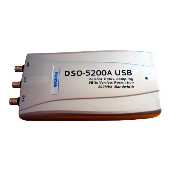
- Page 1 User’s Guide DSO-5200A USB PC Based Digital Oscilloscope Operation Manual...
-
Page 2: Precautions For Safety
The ambient temperature and relative humidity should be 0-40℃ and 10-80% respective for the normal operation of the product. Power Source The USB terminal and DSO-5200A USB are connected via a USB cable for DC +5V power from the PC. The product does not require an outside power source. - Page 3 DSO-5200A USB Manual Handing Precautions The probe ground lead is at ground potential. Do not connect the ground lead to an elevated voltage. Connect the ground lead of the probe to earth ground only. If measuring the floating potential, we will recommend the measurement by the differential motion method using CH1 and CH2.
- Page 4 DSO-5200A USB Manual Hardware Specification Input Max. sample rate Real-time sampling: 250MS/s using one channel, 125MS/s Using two channels Equivalent sampling:50GS/s Channels 2 Channels Bandwidth 200MHz analog bandwidth Vertical resolution 9 bits/channel Gain range 10mV ~ 10V/div @ x1 probe(10mV, 20mV, 50mV,...
- Page 5 DSO-5200A USB Manual 10s,20s,40s,10m,20m,40m,1h /div 1-2-4 sequence) Acquisition mode Equivalent sampling:2ns/div ~ 4us/div Real-time sampling: 10us /div ~ 400ms/div Roll mode: 1s/div ~ 1h/div Range 10 divisions Buffer size 10K ~1M samples Trigger Mode Auto, Normal and Single Type Edge trigger: Rising edge, falling edge.
- Page 6 DSO-5200A USB does not need an external power source, because it is bus-powered from USB Easy to use DSO-5200A USB is easy to use. It is intuitive and easy to understand. Big screen You can change DSO-5200A USB screen size as you need.
- Page 7 1. When manufactured, DSO-5200A USB is calibrated manually to obtain maximum performance. 2. You may calibrate DSO-5200A USB 5 or 6 months after purchase. Probe Compensation 1. You must use a probe with more than 200MHz bandwidth to get undistorted signal.
- Page 8 RIGOL User’s Guide DG1022 Dual-Channel Arbitrary/Waveform Generator Sept. 2011 RIGOL Technologies, Inc.
-
Page 9: The Front/Rear Panel
USB Host LCD Screen Functions Knob Display Mode Waveform Channel Keypad CH2 Output CH2 Output/ Switch Keys Switch Button Counter Input Power Menu Keys CH1 Output CH1 Output Button Connector Figure 1-3 Front Panel for DG1022 © 2008 RIGOL Technologies, Inc. -
Page 10: Rear Panel At A Glance
RIGOL Rear Panel at a Glance 10MHz Synchronous Reference Input Output Power Socket Modulation External USB Device Main Power Input Trig/FSK/Burst Switch Figure 1-4 Rear Panel for DG1022 © 2008 RIGOL Technologies, Inc. -
Page 11: User Interface
Sine which represents the functional key with “Sine” on it on the front panel, while the menu buttons are represented by shadow words such as Freq, which means the “Frequency” option in the Sine menu. © 2008 RIGOL Technologies, Inc. -
Page 12: To Set A Waveform
Square signal with frequency from 1μHz to 5MHz and Frequency/Period, Amplitude/ High Level, Offset/ variable duty cycle. By setting Low level, Duty Cycle and Phase , Square signal with different parameters can be generated. © 2008 RIGOL Technologies, Inc. - Page 13 Frequency/Period, Amplitude/ High Level, Offset/ variable Pulse Width. By setting Low level, Pulse Width/Duty Cycle and Delay , Pulse signal with different parameters can be generated. Figure 1-12 Pulse Signal in the Menu Display Mode © 2008 RIGOL Technologies, Inc.
-
Page 14: Menu Settings
Phase Setting the initial phase of the signal NOTE: Waveforms in single channel needn’t to set the Aligpha parameter. It is always used to align the phases of the two channels’ output signals. © 2008 RIGOL Technologies, Inc. - Page 15 When using the knob to input, use the direction keys to select the digit you want to edit and rotate the knob to change its value. © 2008 RIGOL Technologies, Inc.
-
Page 16: To Set The Output Amplitude
Use the keypad or the knob to input the desired value, choose the unit, and press the corresponding button. Current Parameter: Amplitude Figure 2-3 Setting the Amplitude NOTE: The “dBm” option will appear only when the output impedance is not “High Z”. © 2008 RIGOL Technologies, Inc. -
Page 17: To Set The Offset
Current Parameter: Offset Figure 2-4 Setting the Offset Frequency Amplitude Offset Phase NOTE: The setting of any waveform for the same as sine wave, so we will not cover this topic again. © 2008 RIGOL Technologies, Inc. - Page 18 Current Parameter: Phase Figure 2-5 Setting the initial phase After finishing the above operations, press View, in the Graph Mode, the waveform is shown in the following figure. Figure 2-6 Waveform Parameter in the Graph Mode © 2008 RIGOL Technologies, Inc.
- Page 19 Offset/Low Setting the signal’s Offset or Low Level; the Level current parameter will switch at a second press Duty Cycle Setting the Duty Cycle for Square Waveform Phase Setting the initial phase of the signal © 2008 RIGOL Technologies, Inc.
- Page 20 Duty Cycle: The percentage that the High Level takes up in the whole Period. Please Note : for the Frequency Duty Cycle Value Below 3MHz(included): 20% to 80% From 3MHz to 4MHz (included): 40% to 60% From 4MHz to 5MHz (included): © 2008 RIGOL Technologies, Inc.
-
Page 21: To Set The Duty Cycle
The Generator will change the waveform immediately. Current Parameter: Duty Cycle Figure 2-8 Setting the Duty Cycle Press View, in the Graph Mode, the waveform is shown in the following figure. Figure 2-9 Waveform Parameters in the Graph Mode © 2008 RIGOL Technologies, Inc. - Page 22 Symmetry Setting the Symmetry for Ramp Waveform Phase Setting the initial phase of the signal Term Explanation: Symmetry: The percentage that the Rising Period takes up in the whole Period. Input Range: 0~100% © 2008 RIGOL Technologies, Inc.
-
Page 23: To Set The Symmetry
The Generator will change the waveform immediately. Current Parameter: Symmetry Figure 2-11 Setting the Symmetry Press View, in the Graph Mode, the waveform is shown in the following figure. Figure 2-12 Waveform Parameter in the Graph Mode © 2008 RIGOL Technologies, Inc. - Page 24 Setting the Pulse Width or Duty Cycle of the Pulse DtyCyc Waveform. Delay Setting the Delay time. Term Explanation: Pulse Width: The time span between thresholds of 50% of the rising edge amplitude to the next 50% of the falling edge amplitude. © 2008 RIGOL Technologies, Inc.
- Page 25 Once a parameter is changed, the other one will change accordingly. For instance, the current period is 1ms, the pulse width is 500µs and the duty cycle is 50%, when setting the pulse width to be 200µs, the duty cycle will become 20%. © 2008 RIGOL Technologies, Inc.
- Page 26 The Generator will change the waveform immediately. Current Parameter: Delay time Figure 2-15 Setting the Delay time Press View, in the Graph Mode, the waveform is shown as in the following figure. Figure 2-16 Waveform parameters in the Graph mode © 2008 RIGOL Technologies, Inc.
-
Page 27: Counter Input
Press the Output button to enable/disable the signal output of CH1 or CH2. 2. Counter Input In the Counter mode, the output connector of CH2 is used as the signal input terminal. At the same time, the output of CH2 will be disabled automatically. © 2008 RIGOL Technologies, Inc. - Page 28 (2) Enter “45” from the keypad and choose the unit “°”. The phase is set to be 45°. After finishing the above settings, press View, the output of the Generator is shown as in the following figure. Figure 3-1 Sine Waveform Output © 2008 RIGOL Technologies, Inc.
- Page 29 (2) Enter “30” from the keypad and choose the unit “°” to set the Phase as 30°. After finishing the above settings, press View, the generated waveform is shown in Figure 3-2. Figure 3-2 Square Waveform Output © 2008 RIGOL Technologies, Inc.
- Page 30 (2) Enter “60” from the keypad and choose the unit “°” to set the Phase as 60°. After finishing the above settings, press View, the generated waveform is shown in Figure 3-3. Figure 3-3 Ramp Waveform Output © 2008 RIGOL Technologies, Inc.
- Page 31 (2) Enter “200” from the keypad and choose the unit “μs” to set the Delay as 200μs. After finishing the above settings, press View, the generated waveform is shown in Figure 3-4. Figure 3-4 Pulse Waveform Output © 2008 RIGOL Technologies, Inc.
Need help?
Do you have a question about the DSO-5200A and is the answer not in the manual?
Questions and answers