Advertisement
Quick Links
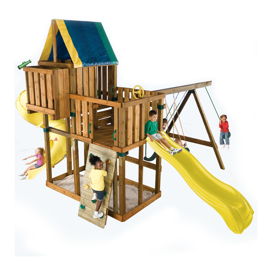
NE 5010
PROJECT 515
ASSEMBLY INSTRUCTIONS
34'
33-1/2'
No. of Children: Up to 10
Min. Use Zone: 34 ' x 33-1/2 '
Set Dim. 22 'W x 21-1/2 'L x 14'H
Est. Building Time: 5-10 hr.
IMPORTANT!!
PLEASE READ BEFORE BEGINNING ASSEMBLY!!
Please make sure all lumber, hardware and accessory parts are accounted for.
DO NOT RETURN
If you are missing anything, please
to the store where purchased.
Please call our Customer Service Department at the number below.
To register your product visit:
http://www.swing-n-slide.com
Other benefits include information on product warranties, assembly plan updates, joining our mailing
list for new products and promotions, receiving our newsletter, and providing feedback on products.
Swing•N•Slide • 1212 Barberry Drive • Janesville, Wisconsin 53545
Visit our web site at: www.swing-n-slide.com or call us at
1-800-888-1232
Advertisement

Related Manuals for Swing-N-Slide Kodiak PROJECT 515


Summary of Contents for Swing-N-Slide Kodiak PROJECT 515
- Page 1 Other benefits include information on product warranties, assembly plan updates, joining our mailing list for new products and promotions, receiving our newsletter, and providing feedback on products. Swing•N•Slide • 1212 Barberry Drive • Janesville, Wisconsin 53545 Visit our web site at: www.swing-n-slide.com or call us at 1-800-888-1232...
-
Page 2: Disposal Instructions
When the equipment is taken out of service, it must be disassembled and disposed of in such a way that no unreasonable hazards will exist at the time the set is discarded. Important! Additional Safety Instructions for all Swing-N-Slide Playground Equipment. - Page 3 Swing-N-Slide® will repair, or at its discretion, replace any part within the stated warranty period which is defective in workmanship or materials. This decision is subject to verification of the defect upon delivery of the defective part to Swing-N-Slide® at 1212 Barberry Drive, Janesville, Wisconsin, 53545. Any part(s) returned to Swing-N-Slide® must have prior approved Return Authorization Number and proof of purchase, including the date of purchase.
-
Page 4: Tools Required
PROJECT 515 TOOLS REQUIRED HAMMER CIRCULAR SAW 1/2” SOCKET & WRENCH ELECTRIC DRILL SAFETY GLASSES CARPENTER’S SQUARE 3/8" DRILL BIT (6" Min.) PHILLIPS BIT TAPE MEASURE & DUST MASK (2) 1/2" panhead screws (4) 1" Truss Screws (2) 5/16" flat washers (6) T- nuts (8) 1-3/4"... - Page 5 AGES 2-10 YEARS For Home / Residential Use ONLY (1) T30 Torx® Bit 1212 Barberry Drive Janesville, WI 53545 1-800-888-1232 www.swing-n-slide.com (1) Name Plate (4) Quick Link (4) 58" Coated Chain weight limit: 115 lbs. (4) Safety Handles (4) Swing Hangers...
- Page 6 PROJECT 515 KODIAK 515 KODIAK 514 8 - 2"X4"X96" OPTIONAL LADDER 2 - 2"X4"X96" 6 - 2"X4"X120" 2 - 2"X4"X120" 12 - 5/4"X6"X120" 10 - 5/4"X6"X144" OPTIONAL ROCK WALL 9 - 4"X4"X96" 2 - 2"X4"X96" 5 - 4"X4"X120" 1 - 2"X4"X120" 3 - 5/4"X6"X120"...
- Page 7 PROJECT 515 39 3/4" 39 3/4" 39 3/4" "X6"X120" 54" 54" "X6"X120" 39 1/2" 39 1/2" 39 1/2" "X6"X120" 39 1/2" 36" 36" "X6"X120" 38 1/2" 38 1/2" 38 1/2" "X6"X120" 43-1/4" 43-1/4" 43-1/4" "X6"X144" 72" 36" 36" "X6"X144" 96" 38 1/2"...
- Page 8 PROJECT 515 How to select the correct fastener Use these 3 pictorial guides to help select the correct fastener(s) for the lumber attachment you are making. Each diagram will highlight the correct number of fasteners to use, and where to attach them. 5/4"...
- Page 9 PROJECT 515 Understanding how the Bracket System Works Example of a Shelf-Loc bracket connection. Shelf-Loc Bracket CORRECT! Wrap-Loc WRONG! Brackets ‘’clipped’’ brackets NOT interlocked! Example of a Shelf-Loc bracket connection. Look for ‘’TOP’’ stamp on bracket for correct orientation. Top of bracket Introduction to the Bracket system 1.
- Page 10 PROJECT 515 4" x 4" x 96" Fig.1 Look for “TOP” Use a 2" lag screw stamp on brackets to hold bracket in while installing. place for later use 2" lag screws per bracket 82-1/2" 55-1/4" 55-1/4" 2" Lag screw A.
- Page 11 PROJECT 515 •WARNING• Avoid splitting your lumber by offsetting your screws at least 3/4" from edge. 2-1/2" screws Fig.1a (1) 2" lag screw (4) 2-1/2" screws A. Frame 1 Construction cont. 2. Attach upper 2" x 4" and lower 5/4" boards as shown in (Fig. 1a) 2"...
- Page 12 PROJECT 515 4’’ x 4’’ x 120’’ Fig.2 Look for “TOP” Use a 2" lag screw stamp on brackets to hold bracket in while installing. place for later use 2" lag screws per bracket 76-3/4" 82-1/2" 2" Lag screw 55-1/4" B.
- Page 13 PROJECT 515 Fig.2a B. Frame 2 Construction cont. 2-1/2" screws 2. Attach upper 2" x 4" and lower 5/4" boards as shown in (Fig. 69-1/2" 62" 2-1/2" screw...
- Page 14 PROJECT 515 Fig.3 Look for “TOP” Use a 2" lag screw stamp on brackets to hold bracket in while installing. place for later use. 4" x 4" x 120" 2" lag screws per bracket 76-3/4" 55-1/4" 2" Lag screw C. Frame 3 Construction 1.
- Page 15 PROJECT 515 Fig.3a 2-1/2" screws C. Frame 3 Construction cont. 2. Attach upper 2" x 4" and lower 5/4’’ boards as shown in (Fig. 3a) 80-1/2" (1) 2" lag screw 2" Lag screw (4) 2-1/2" screws 2-1/2" screw...
- Page 16 PROJECT 515 2-1/2" screws Fig.4 (1) 2" lag screw (4) 2-1/2" screws D. Frame Construction 1. Install 2" x 4" and 5/4" boards as shown above. 2" Lag screw 2-1/2" screw...
- Page 17 PROJECT 515 Fig.4a Double check to make sure structure is square 2-1/2" screws (1) 2" lag screw (4) 2-1/2" screws D. Frame Construction cont. 1. Attach Frame Two as shown above. 2" Lag screw 2-1/2" screw...
- Page 18 PROJECT 515 Tip: Flex brackets to make installation of 4" x 4" easier Fig.5 Fig. 5a Approx. 1/4" E. Install 4x4s 2" Lag Screws 1. Work (2) 4" x 4" into brackets as shown in(Fig. 5), (Fig 5a). 2. Secure brackets (Fig. 5b). 2"...
- Page 19 PROJECT 515 Fig.6 Double check to make sure structure is square F. Attach Frame 3. 1. Attach and secure Frame 3 to rest of unit as shown above. (4) 2" Lag Screws per joint (4) 2-1/2" screws (1) 2" lag screw (Per joint) 2"...
- Page 20 PROJECT 515 Fig.7 2-1/2" screws 2-1/2" screw G. Install Deck Boards 1. Install 5/4" deck boards to structure as shown (Fig. 7). 2. Use two 2-1/2" screws at each end of deck boards. Note: On End Boards, avoid screwing into Shelf Brackets by placing screws behind Shelf Bracket location.
- Page 21 PROJECT 515 Fig.7a 2-1/2" screws 2-1/2" screws H. Center & Entrance Support Boards 1. Install 4" x 4" support boards as shown in (Fig. 7a). 2. Secure bottom of 4" x 4" as shown in (Fig 7a) 2-1/2" screw...
-
Page 22: Bottom View
PROJECT 515 Fig.8 Bottom View Fig.8a 2-1/2" screws 2-1/2" screws (18) 2-1/2" screws 2-1/2" screw I. Center & Entrance Support Boards 1. Construct support boards as shown in (Fig. 8). 2. Secure center of floor boards as shown in (Fig. 8b) 3. - Page 23 PROJECT 515 Fig.9 2-1/2" screws per joint 2-1/2’’ screws 2-1/2" screws 2-1/2" per joint screws J. Install Lower Rail Board 2-1/2" screw 1. Install lower 2" x 4" rail board as shown in (Fig 9). Flush with the sides of 4" x 4" deck supports. NOTE: The bottom screw in the 2"...
- Page 24 PROJECT 515 Tip: Flex brackets to make installation of 4" x 4" easier 1" overhang Fig.10a Approx. 1/4" Allow 4" x 4"s To Overhang 1" Fig.10b 2" Lag screw K. Install 4x4s cont. 1. Work (2) 4" x 4" into brackets as shown in (Fig. 10a), (Fig 10). 2.
- Page 25 PROJECT 515 Fig.11 2-1/2" Screws (2 per joint) FIG. 11a Fig.11a 2" screws 2-1/2" screw L. Install Deck Boards 1. Install 5/4" deck boards to structure as shown (Fig. 11). 2. Use two 2-1/2" screws at each end of deck boards. Where shelf bracket blocks screw path, center board and place one screw on either side.
- Page 26 PROJECT 515 Fig.12 2-1/2" Screws (2 per joint) M. Install Upper Rail Boards 1. Install upper 2" x 4" rail boards as shown in (Fig 12). Flush with the top of 4" x 4" deck supports. 2-1/2" screw...
- Page 27 PROJECT 515 2-1/2" Screws (2 per joint) Fig.13 2-1/2’’ Screws (2 per joint) From opposite side of Filler Boards. 2-1/2" screw N. Install supports 1. Install 2" x 4" as shown in (Fig 13)
- Page 28 PROJECT 515 2-1/2" Screws per joint Fig.14 2-1/2" Screws 2-1/2" Screws (3 per joint) 2-1/2" Screws 2-1/2" screw N. Install supports cont. 1. Install 2" x 4" flush with top of Shelf-Loc Bracket as shown in (Fig 14) 2. Install step as shown in (Fig 14).
- Page 29 Fig.15 Flex brackets to make installation of 4" x 4" easier 2-1/2" Screws Fig. 15a Approx. 1/4’’ 2" Lag Screws Fig.16 O. Install accessory 4x4 1. Work (1) 4" x 4" into brackets as shown in (Fig. 15a), (Fig 15). 2.
- Page 30 PROJECT 515 Optional Laminated Beam NOTE: Lay the lumber on a flat surface before beginning laminated beam assembly. Fig. 17 24" NOTE: Attach one end of the beam with three 2-1/2" screws. Secure boards and attach the other end with three 2-1/2" screws. This will insure that your boards will stay aligned throughout the remainder of the beam assembly.
-
Page 31: Top View
PROJECT 515 Fig. 18 Q. Swing Beam Drill Locations 1. Use a 3/8" drill bit to drill a 3/8" hole through the center of the beam at each location shown in (Fig. 18) 2. Install Swing Hangers onto swing beam at locations shown. Note: Swing Hangers must be installed on same side dimensions were originally marked. - Page 32 PROJECT 515 Hammer Fig. 19 3/8'' hole T-nut t-nut Bottom Beam Clamp (4) 1-1/4'' screws Use Screwdriver to aid in tightening Swing Hanger R. Swing Hanger Installation 1. Tap t-nut into 3/8" hole as shown in (Fig. 19) 2. Place a bottom beam clamp over the swing hanger as shown in (Fig. 19) 3.
- Page 33 PROJECT 515 (8) 2-1/2" Screws S. A-Frame Assembly Fig. 20 1. layout 4" x 4"s as shown in (Fig. 20) 2. Align EZ Frame Bracket with face of 4" x 4"s. 3. Secure EZ Frame Bracket with (8) 2-1/2" screws to 4" x 4"s making sure they are flush with each other.
- Page 34 PROJECT 515 Fig. 22 T-nut Washer 2-1/2" screws 5-1/2" Hex Bolt 2-1/2" screw T. A-Frame Assembly cont. 1. Tap T-nut into 3/8" hole as shown in (Fig. 22) Note: If using Laminated Swing Beam, make sure T-nut teeth do not fall between seams of 2" x 6"s. 2.
- Page 35 PROJECT 515 Fig. 23 U. A-Frame Assembly cont. 1. Position Split-Brackets on 4" x 4" x 56" (Fig 23). 2. With the help of others, lift A-Frame and Swing Beam Assembly and place on to unit as shown in (Fig. 3.
- Page 36 PROJECT 515 (1) 2" x 4" x 71" (2) 2-1/2" Screws (2 per joint) Fig. 25 (4) 5/4" x 6" x 38-1/2" Fig. 25b (6) 5/4" x 6" x 38-1/2" 2" Screws (2 per joint) (6) 5/4" x 6" x 36" Use 2-1/2"...
- Page 37 PROJECT 515 Fig. 26 (3) 5/4" x 6" x 38-1/2" 2" Deck Screws (2 per joint) Fig. 26a V. Barrier Boards cont. 1. Install 5/4" barrier boards evenly spaced in the opening. (2) 5/4" x 6" x 36" 2" Deck Screws (2 per joint) 2-1/2"...
- Page 38 PROJECT 515 Fig.27 2-1/2" Screws W. Support Boards. (3 per joint) 1. Constuct 2" x 4"s as shown in (Fig 27) 1-1/2" 2-1/2" screw...
- Page 39 PROJECT 515 Fig.28 2-1/2" Screws (2 per joint) W. Support Boards. 1. Constuct 2" x 4"s as shown in 2-1/2" screw (Fig 28)
- Page 40 PROJECT 515 Fig. 29 (4) 5/4" x 6" x 39-1/2" 2" Screws (2 per joint) Fig. 30 (4) 5/4" x 6" x 34-3/4" 2" Screws (2 per joint) X. Barrier Boards. 1. Install 5/4" x 6" boards evenly spaced as shown in (Fig 29) and (Fig. 30). 2"...
- Page 41 PROJECT 515 SIDE OPENING OPTION 1...
- Page 42 PROJECT 515 SIDE OPENING OPTION 1 EXAMPLE OF LADDER RUNG INSTALLATION 2-1/2’’ 1-1/4'' screws O. Ladder Assembly. • BOTTOM OF LADDER RAIL • Fig. 32 1. On ladder rails, mark all measurement locations for each side with a pencil. Draw an angle line connecting measurements for each ladder rung alignment.
- Page 43 PROJECT 515 2-1/2" Screws (2 per joint) Fig. 34 Y. Install Tarp. 1. Install tarp as shown in (Fig. 34) 2. Secure tarp in six locations (Fig 34a). 2-1/2" Screws 2-1/2" screw Fig. 34a 1-1/4" screw...
- Page 44 PROJECT 515 Fig. 35 2-1/2" Screws (3 Per joint) 26-1/4" 2-1/2" screw Z1. Install Protective Barrier Board 1. Secure protective 5/4" barrier board as shown in (Fig 35).
- Page 45 PROJECT 515 Fig. 36 Fig. 37 washer 11" 1-3/4" Panhead screw Deck Surface INSTALL PLAY HANDLES HERE 1" Truss Screw Use truss head screws to to secure slide to deck. Slide/Safety Handle Installation. 1. Mount safety handles in the ladder THIS PRODUCT IS INTENDED FOR USE opening approximately 11"...
- Page 46 PROJECT 515 Anchor-It (Sold Seperately) Fig. 38 Flat Washer metal strap 1-1/2" lag bolt Anchor-It stake S. Anchor-It Installation (optional). Instructions for Anchoring Swing•N•Slide Activity Centers 1. Determine the final location of your activity center. 2. Place the Anchor-It stakes adjacent to the base and near the corners of your activity center (at the bottom of the legs on swing sets) and twist the auger-style stakes into the ground until only the loop is exposed.
- Page 47 PROJECT 515 Fig. 39 A2. Unit Modification cont. 2-1/2" screw (1) Install 2" x 4" frame and support as shown in (Fig. 39).
- Page 48 PROJECT 515 Fig. 40a Fig. 40 2-1/2" Screws 2-1/2" screws (Per joint) 2-1/2" Screws 10" (2 Per joint) 5-7/8" 18-1/4" 2-1/2" screw NOTE: 5' Climbing Rock Wall will require Fig. 40b Min. 12 Climbing Rocks (3) Bags of Climbing Rocks. NE 4543S Climbing Wall Lumber Cut List.
- Page 49 PROJECT 515 BACK OPENING OPTION 2 Fig. 41 Fig. 41a NOTE: Remove (3) 5/4" x 6" Barrier Boards 2-1/2" Screws 4-5/8" 20-3/4" 2-1/2" screw NOTE: 7' Climbing Rock Wall will require Fig. 41b 16 Climbing Rocks (4) Bags of Climbing Rocks. NE 4543S Climbing Wall Lumber Cut List.
- Page 50 PROJECT 515 Climbing Rock Fig. 42 (2) "T" nuts 3/8" Holes (2) 2" Hex Head Bolts Hold (rock) (1) Loc Washer per bolt (1) Flat Washer per bolt Climbing Rock Installation 1. Mark locations of Climbing Rocks on the Climbing Wall in a pattern that will easily allow your child to climb to the deck.
- Page 51 PROJECT 515...
- Page 52 Questions???... Call our Customer Service Department at 1-800-888-1232 Swing-N-Slide Printed In China LA 7497...
- Page 53 Swing•N•Slide • 1212 Barberry Drive • Janesville, Wisconsin 53545 Visite nuestro sitio web en www.swing-n-slide.com o llámenos al Visitez notre site Web au www.swing-n-slide.com ou appelez-nous au...
-
Page 54: Instructions Pour La Mise Au Rebut
Lorsque l’équipement est mis hors service, il doit être démonté et conditionné de sorte qu’aucun danger justifié ne sera présent lors de la mise au rebut de l’ensemble. Important! Instructions supplémentaires de sécurité pour tous les centres de jeu Swing-N-Slide. Conserver ce feuillet d’instruction au cas où vous... - Page 55 GARANTIE LIMITÉE DU FABRICANT Swing-N-Slide® Swing-N-Slide® est fière de la qualité et de la durabilité de ses produits. Notre garantie limitée du fabricant donne l’assurance et démontre notre engagement envers la fabrication d’articles pour terrain de jeu résidentiel de qualité.
- Page 56 Cuando el equipo sea retirado de servicio, se debe desarmar y desechar de tal manera que no presente peligros no razonables al momento de desecharlo. ¡Importante! Instrucciones de seguridad adicionales para todos los equipos de juego Swing-N-Slide. Guardar esta hoja de instrucciones en caso de que se requiera contactar al fabricante.
- Page 57 GARANTÍA LIMITADA DE POR VIDA DEL FABRICANTE Swing-N-Slide® garantiza que sus toboganes termoformados y montañas para escalar estarán libres de defectos de mano de obra y materiales, bajo condiciones y uso normales, durante la vida útil del producto.
- Page 58 PROYECTO 515/PROJET 515 HERRAMIENTAS NECESARIAS/OUTILS REQUIS SIERRA CIRCULAR MARTILLO TALADRO ELÉCTRICO DADO Y LLAVE DE 1/2 po (13 mm) SCIE CIRCULAIRE PERCEUSE ÉLECTRIQUE MARTEAU CLÉ ET DOUILLE DE 1/2 po (13 mm) GAFAS DE SEGU RIDAD BROCA DE TALADRO BROCA DE ESTRELLA ESCUADRA DE CARPINTERO CINTA MÉTRICA Y MÁSCARA ANTIPOLVO...
- Page 59 AGES 2-10 YEARS Kodiak For Home / Residential Plan Use ONLY 1212 Barberry Drive Janesville, WI 53545 1-800-888-1232 www.swing-n-slide.com (4) Eslabón rápido (1) broca T30 Torx® (1) placa del nombre (1) plano (1) Foret Torx® T30 (1) Plaque d’identification (1) Plan...
- Page 60 PROYECTO 515/PROJET 515 KODIAK 515 KODIAK 515 8 - 2 x 4 x 96 po (5,1 x 10,2 x 243,8 cm) ESCALA OPCIONAL ÉCHELLE FACULTATIVE 6 - 2 x 4 x 120 po (5,1 x 10,2 x 304,8 cm) 2 - 2 x 4 x 96 po (5,1 x 10,2 x 243,8 cm) 12 - 5/4 x 6 x 120 po (3,2 x 15,2 x 304,8 cm) 2 - 2 x 4 x 120 po (5,1 x 10,2 x 304,8 cm) 10 - 5/4 x 6 x 144 po (3,2 x 15,2 x 365,8 cm)
- Page 61 PROYECTO 515/PROJET 515 39-3/4 po (101 cm) 39-3/4 po (101 cm) 39-3/4 po (101 cm) 5/4 x 6 x 120 po (3,2 x 15,2 x 304,8 cm) 54 po (137,2 cm) 54 po (137,2 cm) 5/4 x 6 x 120 po (3,2 x 15,2 x 304,8 cm) 39-1/2 po (100,3 cm) 39-1/2 po (100,3 cm) 39-1/2 po (100,3 cm)
- Page 62 PROYECTO 515/PROJET 515 Cómo seleccionar el sujetador apropiado Comment choisir le bon système d’attache Utilice estas tres guías ilustradas para seleccionar el (los) sujetador(es) apropiado(s) para el ajuste de maderas que usted está haciendo. Cada diagrama resaltará el número correcto de sujetadores que debe usarse, y dónde fijarlos. Utilisez ces 3 guides illustrés pour faciliter le choix du ou des système(s) d’attache(s) pour l’assemblage de pièces de bois concernées.
- Page 63 PROYECTO 515/PROJET 515 Cómo funciona el sistema de abrazaderas Comprendre le fonctionnement du système de fixation Ejemplo de una conexión con abrazadera de estante. abrazadera de estante Connecteur « Shelf-Loc » Exemple de connecteur « Shelf-Loc ». ¡CORRECTO!/BONNE MÉTHODE! abrazadera de envoltura Connecteur Wrap-Loc ¡INCORRECTO!/MAUVAISE MÉTHODE! abrazaderas entrelazadas...
- Page 64 PROYECTO 515/PROJET 515 Fig.1 (2) 4 x 4 x 96 po (10,2 x 10,2 x 243,8 cm) Busque la marca ‘’TOP’’ sobre las abrazaderas cuando esté realizando la instalación. Recherchez l'estampille « TOP » (dessus) sur les fixations pendant l'installation. Tornillos de compresión de 2 po (5,1 cm) por abrazadera...
- Page 65 PROYECTO 515/PROJET 515 •ADVERTENCIA• 3/4 po (1,9 cm) Evite rajar la madera colocando los tornillos a una distancia de al menos 3/4 po (1,9cm) desde el borde. 3/4 po (1,9 cm) •AVERTISSEMENT!• Évitez de fendre votre pièce de bois en décalant vos vis à...
- Page 66 PROYECTO 515/PROJET 515 (2) 4 x 4 x 120 po (10,2 x 10,2 x 304,8 cm) Busque la marca Fig.2 ‘’TOP’’ sobre las abrazaderas cuando esté realizando (2) Tornillos de la instalación. compresión Recherchez l'estampille de 2 po (5,1 cm) «...
- Page 67 PROYECTO 515/PROJET 515 Fig.2a (3) Tornillos de 2-1/2 po (6,4 cm) Trois (3) Vis de 2-1/2 po (6,4 cm) B. Construcción del marco 2 (cont.) 1. Fije las tablas superiores de 2 x 4 po (5,1 x 10,2 cm) e inferiores de 5/4 po (3,2 cm) como se muestra en la (Fig.
- Page 68 PROYECTO 515/PROJET 515 (3) 4 x 4 x 120 po (10,2 x 10,2 x 304,8 cm) Fig.3 Busque la marca ‘’TOP’’ sobre las abrazaderas cuando esté realizando la instalación. Recherchez l'estampille « TOP » (dessus) sur les fixations pendant l'installation. (2) Tornillos de compresión de 2 po (5,1 cm) por abrazadera...
- Page 69 PROYECTO 515/PROJET 515 Fig.3a Tornillos de 2-1/2 po (6,4 cm) Trois (3) Vis de 2-1/2 po (6,4 C. Construcción del marco 3 (cont.) 2. Fije las tablas superiores de 2 x 4 po (5,1 x 10,2 cm) e inferiores de 5/4 po (3,2 cm) como se muestra en la (Fig.
- Page 70 PROYECTO 515/PROJET 515 Fig.4 Tornillos de 2-1/2 po (6,4 cm) Trois (3) Vis de 2-1/2 po (6,4 (1) Tornillos de compresión de 2 po (5,1 cm) (4) Tornillo de 2-1/2 po (6,4 cm) Une (1) Vis tire-fond de 2 po (5,1 cm) Quatre (4) Vis de 2-1/2 po (6,4 cm) (1) Tornillos de compresión...
- Page 71 PROYECTO 515/PROJET 515 Fig.4a Verifique dos veces Tornillos de que la estructura 2-1/2 po (6,4 cm) Trois (3) esté en escuadra Vis de 2-1/2 po (6,4 Effectuez une double vérification pour vous assurer que la charpente est à l’équerre (1) Tornillos de compresión de 2 po (5,1 cm) (4) Tornillo de 2-1/2 po (6,4 cm) Une (1) Vis tire-fond de 2 po (5,1 cm)
- Page 72 PROYECTO 515/PROJET 515 Consejo: Doble las abrazaderas para facilitar la instalación de los 4 x 4 po (10,2 x 10,2 cm) Conseil : pliez le connecteur pour faciliter l’installation du 4 x 4 po (10,2 x 10,2 cm) Fig.5 Fig. 5a Aprox.
- Page 73 PROYECTO 515/PROJET 515 Fig.6 Verifique dos veces que la estructura esté en escuadra Tornillos de compresión de 2 po (5,1 cm) Effectuez une double vérification por abrazadera pour vous assurer que la Quatre (4) charpente est à l’équerre Vis tire-fond de 2 po (5,1 cm) par fixation (1) Tornillos de compresión...
- Page 74 PROYECTO 515/PROJET 515 Fig.7 5/4 x 6 x 47 po (3,2 x 15,2 x 119,4 cm) (2) Tornillos de 2-1/2 po (6,4 cm) por junta (8) 5/4 x 6 x 54 po (3,2 x 15,2 x 137,2 cm) (2) Vis 2-1/2 po (6,4 cm) par joint Tornillo de 2-1/2 po (6,4 cm) Vis de de 2-1/2 po (6,4 cm)
- Page 75 PROYECTO 515/PROJET 515 Fig.7a (3) Tornillos de 2-1/2 po Trois (3) (6,4 cm) por tabla Vis de 2-1/2 po (6,4 cm) par planche (3) Tornillos de 2-1/2 po (6,4 cm) Trois (3) Vis de 2-1/2 po (6,4 cm) H. Tablas de soporte del centro y de la entrada 1.
- Page 76 PROYECTO 515/PROJET 515 Vista inferior/ Fig.8 Vue du dessous Fig.8a (3) Tornillos de 2-1/2 po (6,4 cm) Trois (3) Vis de 2-1/2 po (6,4 cm) (2) Tornillos de 2-1/2 po (6,4 cm) Deux (2) Vis de 2-1/2 po (6,4 cm) (18) Tornillos de 2-1/2 po (6,4 cm) Dix-huit (18) Vis de...
- Page 77 PROYECTO 515/PROJET 515 Fig.9 Tornillos de 2-1/2 po (6,4 cm) por junta Trois (3) Vis de 2 1/2” par joint Tornillos de 2-1/2 po (6,4 (5) Tornillos cm) por junta de 2-1/2 po (6,4 cm) Trois (3) Cinq (5) Vis Vis de 2-1/2 po de 2-1/2 po (6,4 cm) (6,4 cm) par joint...
- Page 78 PROYECTO 515/PROJET 515 Consejo: Doble las abrazaderas para facilitar la instalación de los 4 x 4 po (10,2 x 10,2 cm) Proyección de 1 po (2,5 cm) Conseil : pliez le connecteur pour Surplomb d'un 1 po (2,5 cm) faciliter l’installation du 4 x 4 po (10,2 x 10,2 cm) Fig.
- Page 79 PROYECTO 515/PROJET 515 Fig.11 Tornillos de 2-1/2 po (6,4 cm) (2 por junta) Vis de 2-1/2 po (6,4 cm) (2 par joint) FIG. 11a Fig.11a Tornillos de 2 po (5,1 cm) Vis de 2 po (5,1 L. Instale las tablas de la plataforma 1.
- Page 80 PROYECTO 515/PROJET 515 Fig.12 Tornillos de 2-1/2 po (6,4 cm) (2 por junta) Vis de 2-1/2 po (6,4 cm) (2 par joint) M. Instale la tabla del riel superior 1. Instale la tabla de 2 x 4 po (5,1 x 10,2 cm) del riel superior como se muestra en la (Fig.
- Page 81 PROYECTO 515/PROJET 515 (2) Tornillos de 2-1/2 po (6,4 cm) (2 por junta) (2) Vis 2-1/2 po (6,4 (2 par joint) Fig.13 (4) Tornillos de 2-1/2 po (6,4 cm) (2 por junta) del lado opuesto de las tablas de relleno. Quatre (4) Vis de 2-1/2 po (6,4 cm) (2 par joint) du côté...
- Page 82 PROYECTO 515/PROJET 515 (4) Tornillos de 2-1/2 po (6,4 cm) (2 por junta) (4) Vis 2-1/2 po (6,4 cm) (2 par joint) Fig.14 Tornillos de 2-1/2 po (6,4 cm) (2) Vis 2-1/2 po (6,4 cm) (6) Tornillos de 2-1/2 po (6,4 cm) (3 por junta) (6) Vis 2-1/2 po...
- Page 83 PROYECTO 515/PROJET 515 Consejo: Doble las abrazaderas para facilitar la instalación de los 4 x 4 po Fig.15 (10,2 x 10,2 cm) Conseil : pliez le connecteur pour faciliter l’installation du 4 x 4 po (10,2 x 10,2 cm) (3) Tornillos de 2-1/2 po (6,4 cm) (3 por junta) (3) Vis 2-1/2 po...
- Page 84 PROYECTO 515/PROJET 515 Viga laminada opcional/Poutre laminée en option NOTA: Disponga la madera sobre una superficie plana antes de iniciar el ensamblaje de la viga laminada. REMARQUE : déposez les pièces de bois d’ceuvre sur une surface horizontale avant de commencer l’assemblage de la poutre laminée. Fig.
- Page 85 PROYECTO 515/PROJET 515 Ubicación de perforación de 3/8 po (9,5 mm) Emplacement des trous de 3/8 po (9,5 mm) fait avec une perceuse Fig. 18 Q. Ubicación de las perforaciones de la viga del columpio 1. Utilice una broca de 3/8 po (9,5 mm) para hacer una perforación de 3/8 po (9,5 mm) a través de la viga en cada lugar que se muestra en la (Fig.
- Page 86 PROYECTO 515/PROJET 515 Martillo Fig. 19 Marteau Orificio de 3/8 po (9,5 mm) Trou de 3/8 po (9,5 mm) Tuerca en T Écrou en T encastré Abrazadera de la viga inferior Attache de base de poutre (4) tornillos de 1-1/4 po (3,2 cm) Quatre (4) vis de Use el destornillador para ajustar 1-1/4 po (3,2 cm)
- Page 87 PROYECTO 515/PROJET 515 R. Disposición del montaje de la estructura en A (8) Tornillos de 2-1/2 po 1. 4 x 4 po (10,2 x 10,2 cm)s como se muestra en la (Fig. 20). (6,4 cm) 2. Alinee la abrazadera del marco EZ con la cara de las piezas de 4 x 4 po (10,2 x 10,2 cm).
- Page 88 PROYECTO 515/PROJET 515 Fig. 22 Tuerca en T Écrou en T encastré Arandela Rondelle Tornillo de 2-1/2 po (6,4 Vis de 2-1/2 po (6,4 cm) Perno de cabeza hexagonal de 5-1/2 po (14 cm) Boulon à tête hexagonale de 5-1/2 po (14 cm) Tornillo de 2-1/2 po (6,4 cm) Vis de de 2-1/2 po (6,4 cm)
- Page 89 PROYECTO 515/PROJET 515 Fig. 23 T. Montaje del marco en A (cont.) 1. Ubique los soportes divisores en la pieza de 4 x 4 x 56 po (10,2 x 10,2 x 142,2 cm) (Fig. 23) 2. Con ayuda de otras personas, levante el marco en A y el conjunto de la viga del columpio y del lugar en la unidad como se muestra en la (Fig.
- Page 90 PROYECTO 515/PROJET 515 (1) 2 x 4 x 71 po (2) Tornillos de 2-1/2 po (6,4 cm) (2 por junta) (5,1 x 10,2 x 180,3 cm) Deux (2) vis de 2-1/2 po (6,4 cm) (2 par joint) Fig. 25 (4) 5/4 x 6 x 38-1/2 po (3,2 x 15,2 x 97,8 cm) Fig.
- Page 91 PROYECTO 515/PROJET 515 Fig. 26 (3) 5/4 x 6 x 38-1/2 po (3,2 x 15,2 x 97,8 cm) (2) Tornillos de 2 po (5,1 cm) (2 por junta) Deux (2) vis de 2 po 5,1 cm) (2 par joint) Fig. 26a V.
- Page 92 PROYECTO 515/PROJET 515 Fig.27 (3) Tornillos de 2-1/2 po (6,4 cm) (2 por junta) (3) Vis de 2-1/2 po (6,4 cm) (2 par joint) 1-1/2 po (3,8 cm) W. Tablas de la barrera (cont.) 1. Construya las tablas de 2 x 4 po (5,1 x 10,2 cm) como se muestra en la (Fig.
- Page 93 PROYECTO 515/PROJET 515 Fig.28 (2) Tornillos de 2-1/2 po (6,4 cm) (2 por junta) (2) Vis de 2-1/2 po (6,4 cm) (2 par joint) W. Tablas de la barrera (cont.) 1. Construya las tablas de 2 x 4 po (5,1 x 10,2 cm) como se muestra en la (Fig.
- Page 94 PROYECTO 515/PROJET 515 Fig. 29 (4) 5/4 x 6 x 39-1/2 po (3,2 x 15,2 x 100,3 cm) (2) Tornillos de 2 po (5,1 cm) (2 por junta) Deux (2) vis de 2 po (5,1 cm) (2 par joint) Fig. 30 (4) 5/4 x 6 x 34-3/4 po (3,2 x 15,2 x 88,3 cm) (2) Tornillos de 2...
- Page 95 PROYECTO 515/PROJET 515 OPCIÓN DE APERTURA LATERAL 1 OUVERTURE LATÉRALE OPTION 1...
- Page 96 PROYECTO 515/PROJET 515 OPCIÓN DE APERTURA LATERAL 1 OUVERTURE LATÉRALE OPTION 1 EJEMPLO DE INSTALACIÓN DE LOS PELDAÑOS DE LA ESCALERA Fig. 32 EXEMPLE D'INSTALLATION DES BARREAUX DE L'ÉCHELLE Esquina superior de 2 x 4 po (5,1 x 10,2 cm) Coin supérieur du 2 x 4 po (5,1 x 10,2 cm) ABRAZADERA DE LA GRADA FIXATION DE LA MARCHE...
- Page 97 PROYECTO 515/PROJET 515 (2) Tornillos de 2-1/2 po (6,4 cm) (2 por junta) Trois (2) Vis de 2-1/2 po (6,4 cm) (2 par joint) Z. Tablas de la barrera Fig. 34 1. Instale dos soportes de techo de 2 x 4 po (5,1 x 10,2 cm) como se muestra en la (Fig.
- Page 98 PROYECTO 515/PROJET 515 Fig. 35 26-1/4 po (66,7 cm) (9) Tornillos de 2-1/2 po (6,4 cm) (3 por junta) Neuf (9) Vis de 2-1/2 po (6,4 cm) (3 par joint) Tornillo de 2-1/2 po (6,4 cm) Vis de de 2-1/2 po (6,4 cm) AA.
- Page 99 PROYECTO 515/PROJET 515 Fig. 36 Fig. 37 Arandela Tornillo con cabeza Rondelle 11 po redonda aplanada de (27,9 cm) 1-3/4 po (4,4 cm) Vis à tête cylindrique Superficie bombée de 1-3/4 po (4,4 de la plataforma Plancher de la terrasse INSTALE AQUÍ...
- Page 100 PROYECTO 515/PROJET 515 Anchor-It Anclaje/« Anchor-It » (Sold Seperately) Fig. 38 arandela plana Rondelle plate correa metálica Courroie de métal Pernos de 1-1/2 po (3,8 cm) 1-1/2 po (3,8 cm) Tire-fond Anclaje « Anchor-It » CC. Instalación del anclaje. Instrucciones para anclar los centros de actividades Swing•N•Slide 1.
- Page 101 PROYECTO 515/PROJET 515 Fig. 39 DD. Modificación de la unidad cont. Tornillo de 2-1/2 po (6,4 cm) (1) Instale el marco de 2 x 4 po (5,1 x 10,2 cm) y el soporte como se Vis de de 2-1/2 po (6,4 cm) muestra en (Fig.
- Page 102 PROYECTO 515/PROJET 515 (11) 5/4 x 6 x 30 po Fig. 40 Fig. 40a (3,2 x 15,2 x 76,2 cm) (4) Tornillos de 2-1/2 po (6,4 cm) ” (4) Vis à terrasse de 2-1/2 po (6,4 cm) (2) Tornillos de 2-1/2 po (1,3 cm) (Por junta) Deux (2) Vis de 2-1/2...
- Page 103 PROYECTO 515/PROJET 515 OPCIÓN POSTERIOR 2 DE LA APERTURA/OPTION ARRIÈRE 2 D'OUVERTURE (16) 5/4 x 6 x 30 po Fig. 41a Fig. 41 (3,2 x 15,2 x 76,2 cm) NOTA: Retire las (3) tablas de 5/4 x 6 po (3.2 x 15.2 cm) de la barrera de protección.
- Page 104 PROYECTO 515/PROJET 515 Climbing Rock Fig. 42 (2) Tuercas en “T” Deux (2) Écrous en « T » (2) Pernos con Agujeros de 3/8 po cabeza hexagonal (9,5 mm)Trous de de 2 po (5,1 cm) 3/8 po (9,5 mm) Deux (2) Boulons à...
- Page 105 PROYECTO 515/PROJET 515...
- Page 106 Questions???... Call our Customer Service Department at 1-800-888-1232 Swing-N-Slide 2015 Impreso en China/ LA 7497 Imprimé en Chine...
Need help?
Do you have a question about the Kodiak PROJECT 515 and is the answer not in the manual?
Questions and answers