
Related Manuals for Gardner Denver RFL Series


Summary of Contents for Gardner Denver RFL Series
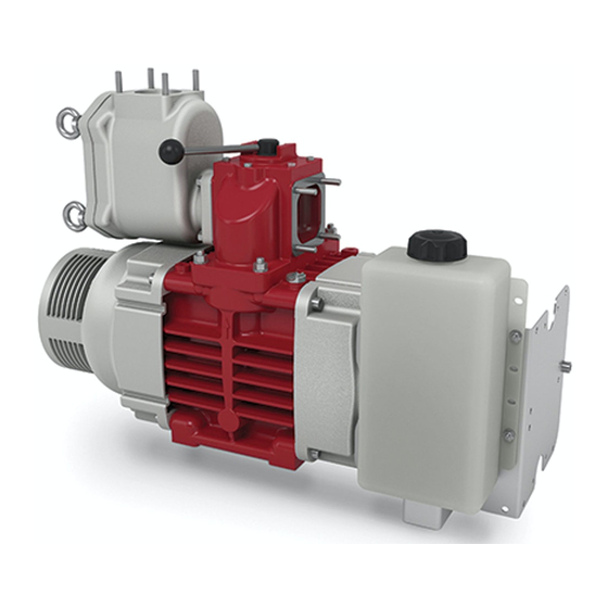
- Page 1 PD BLOWERS & VACUUM PUMPS RFL SERIES Owner’s Manual RFL 102 RFL-7-500 Version 03 April 11, 2018...
-
Page 2: Table Of Contents
TABLE OF CONTENTS HEALTH AND SAFETY .......................... 3 SAFETY RULES & NOTES ON DANGER ..................... 4 2.1 I ........................... 4 NTENDED SAGE 2.2 A & M ........................4 CCEPTANCE ONITORING 2.3 O ..........................4 PERATIONAL AFETY 2.4 E ........................ 4 NVIRONMENTAL ROTECTION 2.5 ATTENTION ............................ - Page 3 INITIAL OPERATION ........................... 19 6.1 C ........................19 HECKING THE YSTEM 6.2 L ..........................19 UBRICATING 6.3 V ..............................19 ALVES 6.4 R ........................... 19 OTATING IRECTION 6.5 D ..............................19 RIVE 6.6 C ..............20 HECKING THE OTATION PEED ACUUM AND RESSURE 6.7 L...
-
Page 4: Health And Safety
Noise Tests carried out by Gardner Denver Drum show that the maximum noise levels for the RFL 102 should typically not exceed 77 dB(A) in the worst case (1500rpm, 2.0 barg). Other vehicle/equipment noise levels are likely to be greater. -
Page 5: Safety Rules & Notes On Danger
2. SAFETY RULES & NOTES ON DANGER Intended Usage The compressor/vacuum pump is designed exclusively for compression or suction of filtered air. Use for any other purpose is not considered intended use. Intended use also requires adherence to the operating data and listed maintenance as set forth in this manual. Acceptance &... - Page 6 All personnel who are required to work with the machine must read the operating instructions, especially the safety instructions, before commencing such work. • Work on the machine must only carried out when the machine is at a standstill. • Before such work begins, measures must be taken to prevent the drive from being switched on.
-
Page 7: Technical Data
3. Technical Data Machine Data The RFL 102 is an air-cooled, oil lubricated rotary vane compressor. On the rating plate of each machine you will find, in addition to the machine number, the most important data. Compressor/Vacuum Pump Units RFL 102 Max. -
Page 8: Dimensions
Dimensions Gearbox Details Fig 3.1 Dimensions of RFL 102 Kit Number TEN009819 Motor Flange Type Hydraulic Drive Details Kit Number TEN009820 Motor Flange Type SAE ‘C’ 4-BOLT Fig 3.2 Hydraulic Drive Dimensions RFL-7-500 Page 7... -
Page 9: Lubrication
Lubrication Lubrication is performed by means of the integrated, fixed drive oil pump. Lubrication oil specification: Single range oils of classes: API: CD/SF and higher MIL-L: 2104 C and higher Compressor/Vacuum Pump Units RFL 102 Oil Tank Capacity l (gal) 4.75 (1.25) Oil Consumption l/h (gal/min) -
Page 10: Transport & Storage
4. Transport & Storage Symbols on the packaging: Fragile Protect from rain Transport Avoid use of force and load/unload packages with care. Attach lifting equipment only to the firmly installed eyebolts. Remove all packaging before installation. Storage Store the machine in a dry and heated room until installation. Remove the covers on inlet and discharge ports only at the time of actual installation. -
Page 11: Installation
5. Installation Fig. 5.1 Machine diagram with a compressor/vacuum pump Vehicle tank with overfill protection Safety vessel with overfill protection Manometer Vacuum relief valve Overpressure safety valve Venting shut-off valve Vacuum intake filter Compressor/Vacuum pump Thermometer Manometer Silencer/Oil separator Fig. 5.2 Machine diagram with a compressor Combination air filter Compressor Thermometer... -
Page 12: Installation Location And Attachment
Thermometer Manometer Silencer/Oil separator Notes • Installation and start-up operation must only be carried out by trained personnel. Gardner Denver will not be liable for warranty claims caused by operator error. • The machine is delivered ready for connection. •... -
Page 13: Prevention Of Suction Intake Of Dirt And Residue
The suction pipe must be of a sufficient size. Its diameter should be at least as given in the following table, otherwise the machine will be overloaded. If the suction pipe is inadequately sized, warranty provided by Gardner Denver will be void. Compressor/Vacuum pump... -
Page 14: Combination Air Filter
Fig. 5.4 Safety Tank Bent inlet pipe Splash sheet Double perforated sheet Drain cock Two ball floats Four guide rods 5.2.5 Combination Air Filter The intake suction air filter designed for the compressor is a dry air filter with an integrated cyclonic pre-cleaner. This filter is particularly suitable for use with intake air with a high dust content. -
Page 15: Safety And Monitoring Features
For compressors: For vacuum pumps: Suction side • Combination air filter • Vacuum filter • Ventilation valve • Vacuum meter Pressure side • Non-return valve • Non-return valve • Thermometer • Thermometer • Manometer • Manometer • Safety valve Contact protection •... -
Page 16: Maintenance Indicator On Suction Air Filter
5.4.4 Maintenance Indicator on Suction Air Filter By means of the optical maintenance indicator fitted to the combination air filter of the compressor, an unacceptable level of contamination of the filter element is indicated in good time. The maintenance indicator must be clearly visible after the combination air filter is fitted. The maintenance indicator must be clearly visible after the combination air filter is fitted. -
Page 17: Oil Level Monitoring
5.4.10 Oil Level Monitoring A mark is cut into the bracket which supports the oil tank. This mark indicates the minimum level of oil required to run the machine. The minimum oil level must be maintained by the operator in accordance with section 7.2 (Oil level). -
Page 18: Flexible Coupling
5.6.2 Flexible Coupling In the case of direct coupling with the drive, e.g. diesel engine, a torsionally flexible coupling must be selected in accordance with the details supplied by the motor manufacturer. This coupling must compensate for the cyclic irregularity of the drive. 5.6.3 Drive Shaft The drive shaft must:... - Page 19 5.6.5 Gearbox • Be mounted on a rigid, structurally sound base plate • Flatness within 0.010 in. • Can be driven by direct coupling, flexible coupling, or V-belt drive • Check oil level every 24 hours of operation. Change oil when gear drive has been in service for 50 hours.
-
Page 20: Initial Operation
6.7, for types of oil. For the RFL 102, single-grade oils are prescribed. Use of multi-grade oils may result in damage to the machine; in addition to this, such use cancels the warranty obligations on the part of Gardner Denver. •... -
Page 21: Checking The Rotation Speed, Vacuum And Pressure
For the RFL 102, single-grade oils are recommended. Use of multi-grade oils can cause damage to the machine. Such use also causes the warranty from Gardner Denver to become void. If the machine is used for suction or compression of gases, please contact us and ask about the correct oils to use! -
Page 22: Operation
7. Operation Start up Normal startup of the compressor/vacuum pump (referred to in the following text as the “machine”) is carried out as described in section Regular Checks During Compression Operation Check operating pressure on the manometer (see rating plate on the machine for the permissible pressure). During Suction Operation Check the operating vacuum on the vacuum meter (see rating plate on the machine for the permissible vacuum). -
Page 23: Ventilation Valve
7.2.2 Ventilation Valve The ventilation valve is the regulator for a vacuum system. When the preset vacuum is reached, it opens and allows the vacuum pump to draw in additional atmospheric air. We recommend the installation of the vacuum meter on the suction port. Check weekly for proper functioning by observing the vacuum meter on the suction port or the compressor/vacuum pump. -
Page 24: Precautions For Long Standstill Periods
Precautions for Long Standstill Periods • Clean the machine thoroughly. If the machine is cleaned with a high pressure jet wash, there is a danger of water intrusion. • After wet cleaning, allow the machine to warm up for a few minutes to prevent the rotor vanes from sticking. If the stoppage of the compressor/vacuum pump installed on the vehicle lasts longer than one month, we recommend operating the machine for at least 15 minutes once a month. - Page 25 Fault Possible cause Elimination • • Compressed air temperature too high Final pressure too high Adhere to nominal pressure • • Exhaust silencer clogged Replace exhaust silencer • • Four-way changeover valve in Put four-way changeover valve incorrect position in correct position •...
-
Page 26: Maintenance
8. Maintenance Warranty We cannot accept liability for damages resulting from failure to observe the installation and operating instructions. Please note that repairs to compressor/vacuum pumps must be carried out only by authorised repair shops using original replacement parts; otherwise, the warranty becomes invalid. You will find a list of our service centres on the back page of the manual. -
Page 27: Cooling System
8.2.1 Cooling System The cooling air must be able to circulate freely. • Check the cooling air inlet/outlet openings every week, and if necessary, remove and clean any dirt and dust deposits. For maximum cooling effectiveness, the air must be able to circulate unhindered. Dirt impairs the cooling effect and can cause the machine to overheat and fail! 8.2.2 Compressor/Vacuum Pump... -
Page 28: V-Belts And V-Belt Tension
To open the filter • Unscrew the 4 off eye nuts (8.1/1) and pull the cover out of the housing (8.1/2). To clean the filter Rinse the filter housing with petrol or cold degreasing solvent. When cleaning the filter housing, under no circumstances must dirt or residue get into the compressor/vacuum pump. -
Page 29: Non-Return Valve
8.2.6 Non-Return Valve No maintenance is necessary for the non-return valve. We recommend a first inspection after 300 hours of operation. Inspect the valve for oil carbon deposits and determine the interval for the next inspection on the basis of the valve condition. The thickness of the oil carbon layer must not exceed 1mm. -
Page 30: Rotor Vane Wear Measurement
8.2.8 Rotor Vane Wear Measurement To inspect the rotor vane wear, remove the reverse flow valve (if fitted) or suction flange. Press the rotor vane in the rotor slot and measure the distance to the rotor surface with a reliable depth gauge (see fig 8.2) Fig. -
Page 31: Service Parts
Installation or attachment of spare parts and additional appliances not supplied by us will invalidate the warranty provided by Gardner Denver. Please note that there are often special manufacturing and delivery specifications for both our own parts and those provided by third parties. - Page 32 Americas Australia Belgium Gardner Denver, Inc. Gardner Denver Ind. Australia Pty Ltd Gardner Denver Belgium N.V. Industrial Products Groups – Americas 30 Bearing Road Luithagen 7A 1800 Gardner Expressway Seven Hills Haven 200 Quincy, IL. 62305 New South Wales B-2030 Antwerpen...
- Page 33 NOTES:...
- Page 34 NOTES:...
- Page 35 NOTES:...
Need help?
Do you have a question about the RFL Series and is the answer not in the manual?
Questions and answers