Table of Contents
Advertisement
Quick Links
Ins. No. C-901TM-2-E
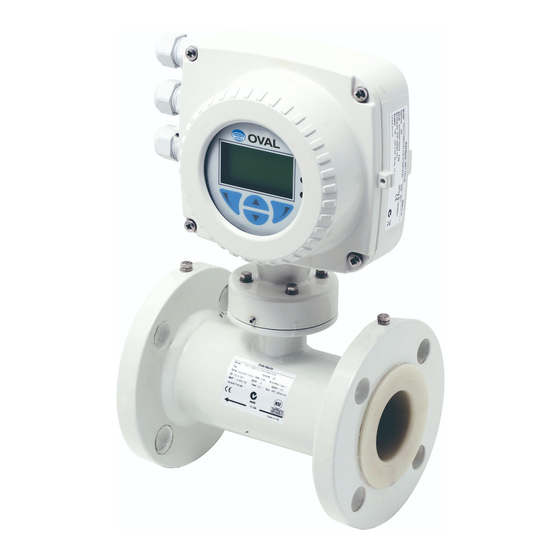
Electromagnetic Flowmeter
WaterMaster 〈Transmitter〉
Thank you for choosing the WaterMaster. This product is manufactured under the stringent quality control
and thoroughly tested and inspected before its shipment from our factory.
This instruction manual is designed to assist the user to obtain the best performance of the product
throughout its service life. In order to take sufficient care, please read this manual carefully before the use
and keep it handy for quick reference.
1
Advertisement
Table of Contents

Related Manuals for Oval WaterMaster


Summary of Contents for Oval WaterMaster
- Page 1 Electromagnetic Flowmeter WaterMaster 〈Transmitter〉 Thank you for choosing the WaterMaster. This product is manufactured under the stringent quality control and thoroughly tested and inspected before its shipment from our factory. This instruction manual is designed to assist the user to obtain the best performance of the product throughout its service life.
-
Page 2: Table Of Contents
C-901TM-2-E CONTENTS 1. SAFETY................................3 1.1 Electrical Safety ............................3 1.2 Symbols ..............................3 1.3 Health and Safety Considerations ......................4 2. MECHANICAL INSTALLATION ........................5 2.1 Installation Conditions ..........................5 2.2 Outline Dimensions ..........................7 3. ELECTRICAL INSTALLATION ........................8 3.1 Separately Mounted Transmitter/Sensor Arrangement ................8 3.2 Transmitter Terminal Connection ......................8 3.3 Cable Preparation (Separately Mounted Transmitter only) ..............9 3.4 Sensor Cable Connection (Separately Mounted Transmitter) ..............10 3.4.1 Sensor Cable Terminal Connection and Recommended Cable Length ........10... -
Page 3: Safety
This instrument complies with the requirements of CEI/IEC 61010-1:2001-2 "Safety Requirements for Electrical Equipment for Measurement, Control and Laboratory Use", NIST, and OSHA. Refrain from using the instrument in a way not specified by OVAL, or protection of the instrument may be ruined. 1.2 Symbols Below are the meaning of symbols indicated on the product label. -
Page 4: Health And Safety Considerations
・Do not mix two chemicals when disposing. ・Product liability - advice and support provided free of charge are offered in good faith; OVAL will not be held liable, however. If safety advice regarding the use of the product written in this manual or relevant hazard data sheets (if applicable) is required, contact OVAL. -
Page 5: Mechanical Installation
C-901TM-2-E 2. MECHANICAL INSTALLATION 2.1 Installation Conditions Secure sufficient space for reading display. Fig. 2.1 Location selection 60/70℃ (Integrally mounted/ Separately mounted) Min. -20℃ Fig. 2.2 Operating temperature range (ambient) Fig. 2.3 Shade Fig. 2.4 Vibration... - Page 6 C-901TM-2-E Fig. 2.5 Leakage Submersion duration of transmitter: 1m < 12hours (accumulated time) IP67 (NEMA 4X) Fig. 2.6 Degree of protection Position accessible to transmitter Fig. 2.7 Access to transmitter...
-
Page 7: Outline Dimensions
C-901TM-2-E 2.2 Outline Dimensions Unit: mm Fig. 2.8 Dimension of integrally mounted transmitter Unit: mm R3.2 Fig. 2.9 Dimension of separately mounted transmitter CAUTION: Install the separately mounted transmitter in stable place using three M5 screws. (M5 screws are not provided as accessories.) -
Page 8: Electrical Installation
C-901TM-2-E 3. ELECTRICAL INSTALLATION 3.1 Separately Mounted Transmitter/Sensor Arrangement CAUTION: Cable for bonding connection must be 4mm (< 10AWG) or more. Power supply Fig. 3.1 Separately mounted transmitter installed on roadside cabinet 3.2 Transmitter Terminal Connection WARNING: Isolate the transmitter from the power supply device before detaching the front cover. ○... -
Page 9: Cable Preparation (Separately Mounted Transmitter Only)
C-901TM-2-E Refer to Fig. 3.2. 1. Loosen four screws on the front cover without removing them. 2. Detach the front cover. 3. Confirm that power indicator (LED) on the backplane is turned off. WARNING: While power indicator (LED) is turned on, power is still supplied to the transmitter. Isolate the power supply from the transmitter before proceeding further. -
Page 10: Sensor Cable Connection (Separately Mounted Transmitter)
C-901TM-2-E 3.4 Sensor Cable Connection (Separately Mounted Transmitter) Make the connection as instructed as follows: CAUTION: 1. Make sure to use the cable included with the product. 2. Bundle screen wires D1/TFE (Orange) and D2 (Yellow) with outer drain wire by twisting, then cover the bundle with a sleeve (Green/Yellow). -
Page 11: Output Connection
C-901TM-2-E 3.5 Output Connection 1. To limit voltage fluctuation, inductive load needs to be suppressed. CAUTION: 2. Setting of output operation can be changed through parameter. 3. Pulse and alarm circuits are electrically separated from all other outputs. External isolator is normally unnecessary. 3.5.1 Pulse Output PLC or Datalogger XX XX ... -
Page 12: Alarm Output/Logic Output
C-901TM-2-E Forward flow output (DO1) Counter/totalizer ‒ XX XX XX XX 42 41 51 61 1 2 3 4 5 6 52 62 Reverse flow output (DO2) Counter/totalizer COM DO1 DO2 ‒ 1 2 3 4 5 6 Fig. 3.7 Remote measurement/electric counter etc. connection 3.5.2 Alarm Output/Logic Output XX XX ... - Page 13 C-901TM-2-E Bell Alarm 1 DC power supply XX XX XX XX 42 41 51 61 52 62 and / or Horn DO1 DO2 Alarm 2 Fig. 3.9 Alarm/logic output connection CAUTION: 1. Regular alarm/log output uses DO3 (terminal 61). DO1 (41) and DO2 (51) may also be set as alarm/logic output if necessary.
-
Page 14: Current Output (4 To 20Ma) - Hart (Fex100) Variant
C-901TM-2-E CAUTION: 1. Digital outputs of WaterMaster are NPN optocoupled transistors used as switches. 2. Maximum allowable voltage of collector is 30V DC. 3. Maximum allowable current across both ends of transistor is 220mA. 3.5.3 Current Output (4 to 20mA) - HART (FEX100) Variant Refer to the Programing Guide for details of HART protocol communication. -
Page 15: Power Supply Connections
C-901TM-2-E 3.6 Power Supply Connections WARNING: 1. Electrical installation and earth grounding must be implemented in compliance with relevant national and regional standards. 2. Power supply must be connected through suitable isolator and fuses must be installed in compliance with relevant standards. 3. -
Page 16: Dc Power Supply
C-901TM-2-E 3.6.2 DC Power Supply Power indicator LED DC fuse F2 2A Type T Internal ground screws Power supply + Power supply − External ground screw > 4 mm (< 10 AWG)Copper wire DC power supply through suitable isolator and fuse Transmitter label (DC) Fig. 3.14 DC power supply connection... -
Page 17: Dip Switches For Setting
C-901TM-2-E 3.6.3 DIP Switches for Setting Three DIP setting switches are installed on backplane board of the transmitter. Following is the factory setting of these switches: 1. Separately mounted transmitter - All OFF 2. Integrally mounted transmitter - SW3 ON DIP setting switches Function of DIP switches... - Page 18 C-901TM-2-E 1. Check label on the side of the cartridge and confirm that the cartridge to be installed is of the correct power supply device and communication bus type (Standard: HART communication). - An AC cartridge has a black label on its side. - A DC (and low voltage AC) cartridge has two red DC labels;...
-
Page 19: Start-Up And Operation
C-901TM-2-E 4. START-UP AND OPERATION CAUTION: This section explains the options available in "Easy Setup" menu. For details of other menus and operating levels, refer to Programing Guide. 4.1 Menu and Parameter Navigation All system commands and selections can be executed by scrolling between menus using four keys under the display. -
Page 20: Start-Up Screens
C-901TM-2-E 4.2 Start-up Screens At start-up, system status is indicated by the displayed screen type. Following are four common start-up screen types: System Startup System Startup LOADING SYSTEM DATA A progress bar is displayed during system start-up to indicate the duration of start-up process. System Startup Upon completion of system start-up, one of the four following LOADING SYSTEM DATA... - Page 21 C-901TM-2-E System Startup INSTALLATION CHANGED INSTALLATION CHANGED If the sensor data stored in the transmitter memory does Identify Changed Item System Startup not match the data on the connected sensor, a warning INSTALLATION CHANGED "INSTALLATION CHANGED" will be displayed. Sensor Transmitter Identify Changed Item By specifying the items to change (Transmitter or Sensor), following data will be copied: Sensor Transmitter...
-
Page 22: Security Levels And Access By Passwords
C-901TM-2-E 4.3 Security Levels and Access by Passwords During start-up, "Start-up Display" and "Process Display" screens become active in sequence. 1. Passwords at levels "Standard" and "Advanced" are available for end-users to CAUTION: set and change. 2. Access to "Service" level is for factory-personnel only and not available to end- users. -
Page 23: Default Passwords
C-901TM-2-E 4.3.1 Default Passwords Default passwords are provided to the WaterMaster transmitter for access to "Standard" and "Advanced" level menus. The two passwords are as follows: ・"Standard" access password: 2 ・"Advanced" access password: 3 CAUTION: Some products are not provided with default passwords. -
Page 24: Easy Setup
C-901TM-2-E 4.4 Easy Setup Menu Easy Setup Easy Setup The "Easy Setup" level is used for quick system setup and a set of options for users with "Standard" and "Advanced" access permits. Users with "Read Only" access permit cannot select this Exit Select level. -
Page 25: General Specifications
Description Liquids equivalent to water (Clean water, wastewater, industrial water, river water, etc.) Note: For slurries and Applicable fluids corrosive fluids, contact OVAL representative. 40, 50, 80, 100, 250, 300, 350, 450, 500, 600, 700, 750, 800, 900, 1000, 1100, 1200,... -
Page 26: Flow Range
C-901TM-2-E 6. FLOW RANGE Settable range[m /h] Nom. size Guaranteed flow range [mm] [m /h] Min. Range Max. Range 0.02 to 6.3 0.02 to 0.126 0.02 to 12.6 0.032 to 10 0.032 to 0.2 0.032 to 20 0.05 to 16 0.05 to 0.32 0.05 to 32 0.13 to 40... -
Page 27: Product Code Explanation
Description JIS10K ① ② ③ ④ ⑤ ⑥ ⑦ ⑧ ⑨ ⑩ ⑪ ⑫ ⑬ ⑭ ⑮ FEV111 FEW311 FEW321 equivalent WaterMaster Nom. size 25mm or smaller and 250mm or bigger ○ ○ ○ Model WaterMaster Nom. size 40mm or bigger and 200mm or smaller ○... - Page 28 C-901TM-2-E 2017.04 Revised △ 2015.06 Released All specifications are subject to change without notice for improvement. C-901TM-2-E(1) OVAL Corporation Head Office: 10-8, Kamiochiai 3-chome, Shinjuku-ku, Tokyo, Japan Phone. 81-3-3360-5121 Fax. 81-3-3365-8605...
Need help?
Do you have a question about the WaterMaster and is the answer not in the manual?
Questions and answers