Table of Contents
Advertisement
Quick Links
Advertisement
Table of Contents

Related Manuals for FAAC MSE 110 W


Summary of Contents for FAAC MSE 110 W
- Page 1 MSE 110 W MSE 110 W...
- Page 2 8 11 IDENTIFICATION OF THE SYSTEM ........................p. 8 12 INSTALLATION OF FIXED RECEIVER ON SAFEBEAM COLUMN ............... p. 9 FAAC S.p.A. Via Benini, 1 40069 Zola Predosa (BO) - ITALIA Tel.: 051/61724 - Fax: 051/758518 www.faac.it 7325291 Rev. B...
-
Page 3: Ce Declaration Of Conformity
Address: Via Benini, 1 - 40069 Zola Predosa BOLOGNA - ITALY Declares that: The opto-electronic active protection device mod. MSE 110 W, • conforms to the essential safety requirements of the following EEC directives: EN 12978 - Category 2 73/23/EEC and subsequent amendment 93/68/EEC. - Page 4 -20 ÷ +55 (MSE 110 W). Protection class (IP) MSE 110 W is a safety device conforming to European Standard EN 12978 category 2, and can be installed ONLY for protecting the Sensitive edge detection time (msec) primary edge (opening or closing) of the mobile leaf of a sliding Photocell detection time (msec) gate.
-
Page 5: Operation
INSTALLING THE DEVICE OPERATION TYPES OF INSTALLATION The infra-red ray transmitters (TX1 and TX2), inside the sensitive edge, The fixed receiver can be installed by using various solutions, communicate with the central receiver-transmitter which, in turn, according to the type of sliding gate. communicates with the fixed receiver (RX3). -
Page 6: Installation Sequence
POSITIONING AND SIZING THE COMPONENTS Top rubber profile L1: When you have chosen the type of installation for the fixed receiver, L1 = X + T - HT - 63,5 size the components as described below. where: 5.2.1 Positioning the fixed receiver X = Total length of finished edge (max. - Page 7 5.3.2 Installing the rubber profiles and the 5.3.3 Installing the closing caps receiver-transmitter Fit the closing caps, checking if they are in contact with the rubber Fit the batteries (supplied standard) in the top and bottom profiles, and secure them with the self-tapping screws (supplied transmitters, observing correct polarity as indicated on the standard) in the pre-drilled holes.
-
Page 8: Electrical Connections
5.3.5 Installing the coupling profile ELECTRICAL CONNECTIONS The coupling profile and its aluminium profile must be cut to at Make the electrical connections on the terminal-board of the least the same length as the finished edge (dimension X in Fig. 5). fixed receiver, consulting the instructions of the control units, in the different configurations. -
Page 9: Final Operations
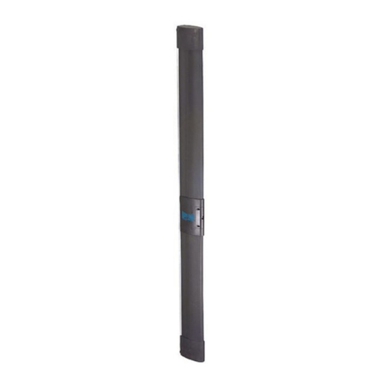
If this procedure is not observed, this will render the system’s conformity certificate invalid. Correctly instruct the persons using the gate about the operation of protective device MSE 110 W. Fig. 12 Hand the User’s Guide to the end-user. REPLACING THE BATTERIES Use lithium batteries model AA - L91 - 1.5V. - Page 10 12 INSTALLATION OF FIXED RECEIVER ON SAFEBEAM COLUMN To install the column, consult instructions for the accessory. To install the fixed receiver, proceed as shown in Fig. 12: 1. Shorten the front housing (ref. ) of the column (ref. ) by 29 mm. 2.
- Page 11 DESCRIPTION Safety edge MSE 110 W is a safety device conforming to European Standard EN 12978 category 2, and can be installed ONLY to protect the primary edge (for opening and closing) of the mobile leaf of a sliding gate.
- Page 14 Les descriptions et les illustrations du présent manuel sont fournies à titre indicatif. FAAC se réserve le droit d’apporter à tout moment les modifications qu’elle jugera utiles sur ce produit tout en conservant les caractéristiques essentielles, sans devoir pour autant mettre à...
Need help?
Do you have a question about the MSE 110 W and is the answer not in the manual?
Questions and answers