Table of Contents
Advertisement
Quick Links
Advertisement
Table of Contents

Related Manuals for FAAC MSE 110 W

Summary of Contents for FAAC MSE 110 W
- Page 1 MSE 110 W MSE 110 W...
-
Page 2: Table Of Contents
5.3.4. INSTALLING THE FIXED RECEIVER ........................p. 6 5.3.5. INSTALLING THE COUPLING PROFILE ....................... p. 6 6. ELECTRICAL CONNECTIONS ......................p. 7 7. OPERATION DIAGNOSTICS ......................p. 7 FAAC S.p.A. Via Benini, 1 40069 Zola Predosa (BO) - ITALIA Tel.: 051/61724 - Fax: 051/758518 www.faac.it... -
Page 3: Declaration Of Conformity
73/23/EEC and subsequent amendment 93/68/EEC. 89/336/EEC and subsequent amendment 92/31/EEC and 93/68/EEC Additional information: This product underwent a test in a typical, uniform configuration. (all products manufactured by FAAC S.p.A): Bologna, 01 January 2006. The Managing Director A. Bassi WARNINGS Attention! For the safety of people, it is important that all the instructions be carefully observed. -
Page 4: Dimensions
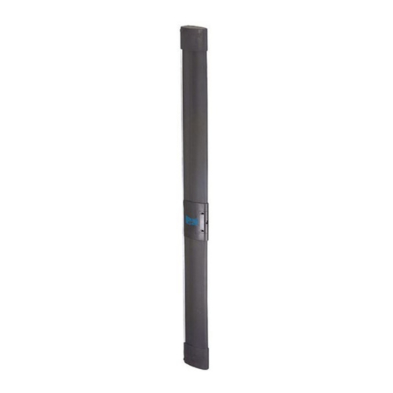
These instructions are valid for the FAAC Mobile Safety Edge ° [ (MSE 110 W). MSE 110 W is a safety device conforming to European Standard t i s EN 12978 category 2, and was designed to protect the primary edge (for opening and closing) of the mobile leaf of a sliding gate. -
Page 5: Operation
INSTALLING THE DEVICE OPERATION 5.1. TYPES OF INSTALLATION The infra-red ray transmitters (TX1 and TX2), inside the sensitive The fixed receiver can be installed by using various solutions, edge, communicate with the central receiver-transmitter which, according to the type of sliding gate. in turn, communicates with the fixed receiver (RX3). -
Page 6: Positioning And Sizing The Components
5.2. POSITIONING AND SIZING THE COMPONENTS Top Rubber profile L1: When you have chosen the type of installation for the fixed L1 = X + T - HT - 63.5 receiver, size the components as described below. where: 5.2.1. Positioning the fixed receiver X = Total length of finished edge (max. -
Page 7: Installing The Rubber Profiles And The Receiver/Transmitter
5.3.2. Installing the rubber profiles and the receiver/ 5.3.4. Installing the fixed receiver transmitter. Position the receiver so that the lens on the front panel (Fig. 8 ref. Fit the batteries (supplied standard) in the top and bottom ) is 50-55 cm from the ground (HT see Fig. 5): transmitters, observing correct polarity (TX1 and TX2 Fig. -
Page 8: Electrical Connections
• 7. OPERATING DIAGNOSTICS If you use this profile to install the fixed receiver, you must cut The 6 LEDs on the fixed receiver make it possible to diagnose the front rubber element to create a niche for housing the installation and correct operation of all the devices of safety receiver at a height of 50 - 55 cm off the ground, using the supplied drilling template (see Fig. - Page 10 Les descriptions et les illustrations du présent manuel sont fournies à titre indicatif. FAAC se réserve le droit d’apporter à tout moment les modifications qu’elle jugera utiles sur ce produit tout en conservant les caractéristiques essentielles, sans devoir pour autant mettre à...
Need help?
Do you have a question about the MSE 110 W and is the answer not in the manual?
Questions and answers