Table of Contents
Advertisement
Quick Links
Advertisement
Table of Contents

Related Manuals for Optimum OPTI turn TU 3008G


Summary of Contents for Optimum OPTI turn TU 3008G
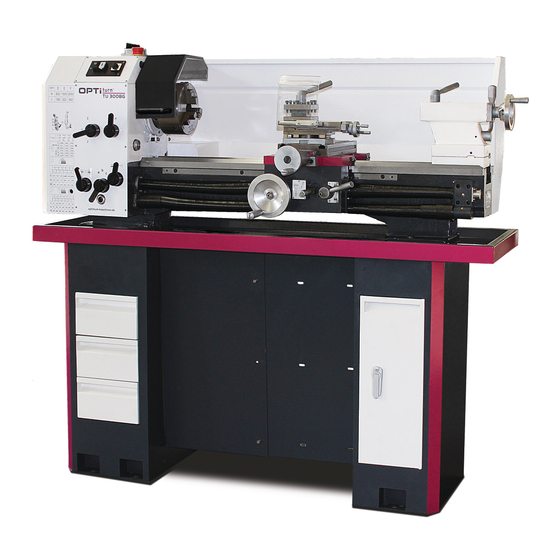
- Page 1 Operating Manual Version 1.1.6 Lathe (L691) Part no. 3427210...
-
Page 2: Table Of Contents
Table of contents Safety Rating plate..............................6 Safety instructions (warning notes)........................ 7 1.2.1 Classification of hazards ........................7 1.2.2 Pictograms ............................7 Intended use ..............................8 Reasonably foreseeable misuses........................9 1.4.1 Avoiding misuse ..........................9 Potential dangers that can be caused by the lathe..................9 Qualification .............................. - Page 3 Safety ................................26 4.2.1 Overview of the control elements ....................26 4.2.2 Overview of indicator elements.......................27 4.2.3 Control elements..........................28 Switching on the machine ..........................28 4.3.1 Switching on ...........................28 Switching the machine off ..........................29 Resetting an emergency stop condition .......................29 Resetting the motor circuit breaker ......................29 Power failure, Restoring readiness for operation ..................29 Speed setting ...............................30 Fixing the lathe saddle ..........................30...
- Page 4 Check up, inspection and maintenance....................... 68 Repair ................................74 5.3.1 Customer service technician ......................74 Ersatzteile - Spare parts Ersatzteilbestellung - Ordering spare parts ....................75 Hotline Ersatzteile - Spare parts Hotline...................... 75 Service Hotline............................. 75 Ersatzteilzeichnungen - Spare part drawings ....................76 Schaltplan - Wiring diagram.........................
- Page 5 Dear customer, Thank you very much for purchasing a product made by OPTIMUM. OPTIMUM metal working machines offer a maximum of quality, technically optimum solutions and convince by an outstanding price performance ratio. Continuous enhancements and pro- duct innovations guarantee state-of-the-art products and safety at any time.
-
Page 6: Safety
Safety Glossary of symbols provides further instructions calls on you to act listings This part of the operating instructions explains the meaning and use of the warning notes included in these operating instructions, defines the intended use of the lathe, ... -
Page 7: Safety Instructions (Warning Notes)
Safety instructions (warning notes) 1.2.1 Classification of hazards We classify the safety warnings into different categories. The table below gives an overview of the classification of symbols (ideogram) and the warning signs for each specific danger and its (possible) consequences. Symbol Signal word Definition / consequence... -
Page 8: Intended Use
Technical specification on page 16 In order to achieve optimum cutting performance, it is essential to choose the right turning tool, feed, tool pressure, cutting speed and coolant. WARNING! Extremely severe injuries due to non-intended use. -
Page 9: Reasonably Foreseeable Misuses
Reasonably foreseeable misuses Any other use other than that specified under "Intended use" or any use beyond the described use shall be deemed as non-intended use and is not permissible. Any other use has to be discussed with the manufacturer. The lathe must not be used to process metal, cold and non-inflammable materials. -
Page 10: Qualification
and strictly follow these operating instructions. In the event of improper use there may be a risk to the persons, there is a risk of damage to the lathe and other property, the correct function of the lathe may be affected. ... -
Page 11: Safety Measures During Operation
Safety measures during operation CAUTION! Danger due to inhaling dust and mist that is hazardous to health. Dependent on the material which need to be processed and the used auxiliaries dusts and mist may be caused which might impair you health. Make sure that the generated health hazardous dusts and mist are safely sucked off at the point of origin and is dissipated or filtered from the working area. -
Page 12: Emergency-Stop Switch
WARNING! The protective equipment for material separation that is made available and delivered together with the machine is designed to reduce the risk of workpieces or fractions of them being expelled from the machine, but not to remove them entirely. 1.9.1 Emergency-stop switch CAUTION! -
Page 13: Lathe Chuck Protection With Position Switch
1.9.3 Lathe chuck protection with position switch The lathe is equipped with a lathe chuck protection. The spindle of the lathe can only be switched on if the lathe chuck protection is closed. Lathe chuck protection Img.1-3: Lathe chuck protection 1.9.4 Protective cover lead screw and feed rod The lead screw and the feed rod of the lathe is covered with a coil spring as a protective cover. -
Page 14: Personal Protective Equipment
General check Equipment Check Signs, Installed and legible Markers Functional check Equipment Check Emergency-stop After activating the emergency stop mushroom button, the control voltage on mushroom switch the lathe will shut off. The spindle continues to rotate for a while, depending on the mass moment of inertia of the spindle and workpiece. -
Page 15: Disconnecting And Securing The Lathe
Clamp the turning tool at the correct height and with the least possible overhang. Turn off the lathe before measuring the workpiece. The instructions described in these operating instructions must be strictly observed during assembly, operation, maintenance and repair. Do not work on the lathe if your concentration is reduced, for example, because you are ... -
Page 16: Technical Specification
Technical specification The following information represents the dimensions and indications of weight and the manufacturer‘s approved machine data. 3x400V ~ 50Hz ( ~ 60 Hz ) Electrical connection 1.1 KW Drive motor power Work areas Center height [ mm ] Distance between centres [ mm ] Swing diameter over machine bed [ mm ] Swing diameter over cross slide [ mm ]... -
Page 17: Slides
Slides Travel cross slide [mm] Scale on the handwheel cross slide 4mm/rev - splitting 0.04mm Travel top slide [mm] Scale on the handwheel top slide 2mm/rev - splitting 0.02mm Scale on the handwheel lathe saddle 5mm/rev - splitting 0.5mm maximum dimension for lathe tool in quadruplicate tool holder [mm] Tailstock Quill diameter [mm]... -
Page 18: Delivery, Interdepartmental Transport And Unpacking
Delivery, interdepartmental transport and unpacking CAUTION! Injuries caused by parts falling over or off a forklift, pallet truck or transport vehicle. Only use means of transport that can carry the total weight and are suitable for it. Notes on transport, installation and unpacking Improper transport of individual devices and minor machines, unsecured devices and minor machines stacked on top of each other or next to each other in packed or already unpacked condition is accident-prone and can cause damage or malfunctions for which we do not grant... -
Page 19: Delivery
Delivery INFORMATION The machine is pre assembled. It is delivered in a transport box. After the unpacking and the transportation to the installation site it is necessary to mount and assemble the individual components of the machine. Check the status of the machine immediately upon receipt and claim possible damages at the last carrier also if the packing is not being damaged. -
Page 20: Lifting With Lifting Equipment
Img.3-1: Load suspension point 3.2.2 Lifting with lifting equipment Fasten the load suspension gear as presented in Img.3-1: Load suspension point Make sure that you distribute the loads evenly so that the lathe cannot turn over while lifting. -
Page 21: Machine Center Of Gravity
Machine Center of Gravity 3.3.1 without a machine base 1525 1420 Schwerpunkt / Centre of gravity TU3008G Version 1.1.6 - 2021-9-17 Translation of original instruction... -
Page 22: With An Optional Machine Base
3.3.2 with an optional machine base CAUTION! In order to provide for the necessary stability of the machine with an optional machine base, it is necessary to firmly fasten the machines to the base. The machine base itself must be affixed firmly to the floor. -
Page 23: Cleaning The Machine
The substructure must be prepared in such a way as to ensure that, if any lubricant is used, it cannot penetrate the floor. Protruding parts - such as the dog, handles, etc. - must be secured, where necessary, by ... -
Page 24: Electrical Connection
Risk from using improper workpiece clamping materials or operating the machine at an inadmissible speed. Only use the tool clamping devices (e.g. lathe chuck) that were delivered with the machine or those offered by OPTIMUM as optional equipment. Only use tool clamping devices in the intended admissible speed range. Electrical connection The machine is installed ready for operation with a 400V three-phase plug. -
Page 25: Operation
Operation Control and indicating elements Img.4-1: TU3008G Pos. Designation Pos. Designation Rotation direction switch Emergency-stop button ON/ OFF switch Selector lever speed adjustment Lathe chuck protection Protective cover of the headstock Change wheel and feed table Selector switch for feed direction Selector switch, longitudinal feed with lead screw, Selector switch for feed speed cross feed with feed rod... -
Page 26: Safety
Safety Commission the lathe only under the following conditions: The lathe is in proper working order. The lathe is used as prescribed. Follow the operating instructions. All safety devices are installed and activated. Eliminate or have all malfunctions rectified promptly. Stop the lathe immediately in the event of any abnormality in operation and make sure it cannot be started-up accidentally or without authorisation. -
Page 27: Overview Of Indicator Elements
Tailstock Tool holder Attachment screw lathe saddle 4.2.2 Overview of indicator elements Scale cross offset tailstock ( 1 ) Oil sight glass speed gear unit ( 2 ) Oil sight glass feed gear Operation TU3008G Version 1.1.6 - 2021-9-17 Translation of original instruction... -
Page 28: Control Elements
4.2.3 Control elements Turning direction Spindle rotation On / Off Inch thread [ threads / inch ] Longitudinal feed / cross feed mm per spindle revolution Metric thread [ mm / spindle revolution ] Feed direction Oil fill, oiling Position clamp bolt on the lathe spindle holding fixture Switching on the machine 4.3.1 Switching on... -
Page 29: Switching The Machine Off
Switching the machine off Press push button "Off" or set the rotation direction switch to the neutral central position. If the lathe has been shut off for a longer period of time, switch it off using the main switch and secure it against being unintentionally switched on again or pull the power plug. -
Page 30: Speed Setting
Speed setting ATTENTION! Only change gear positions when the lathe is being completely stopped. A speed change is done by setting the shift lever at the speed gear unit. Fixing the lathe saddle ATTENTION! The cutting force produced during facing, recessing or slicing process may displace the lathe saddle. -
Page 31: Changing The Change Gears
4.10.2 Changing the change gears The change gears for the feed are mounted on a quadrant. Disconnect the machine from the electrical supply. Loosen the locking screw on the quadrant with a hexagon key. Locking screw (Hexagon key) Img.4-4: Locking screw quadrant ... - Page 32 Loosen the clamping screws on the quadrant. Clamping bolts Img.4-6: Attachment of change gears Install the gear couples using the feed or change gear table and screw the gearwheels onto the quadrant again. Swing the quadrant to the left until the gearwheels have engaged again. ...
-
Page 33: Feed Table, Table For Thread Cutting
4.10.3 Feed table, table for thread cutting The tables are built up in a way that you may later on assemble the required combination to cut a thread without having to look up the details. Ligature as orientation for the caming of one toothed wheel to the following one. -
Page 34: Tool Holder
INFORMATION Move the hand wheel of the lathe saddle a little in order to facilitate the locking of the engaging lever. 4.12 Tool holder Clamp the lathe tool into the tool holder. The lathe tool needs to be clamped as short and tight as possible when turning in order to be able to absorb the cutting force during the chip formation well and reliably. -
Page 35: Adjusting The Camlock Bolts To The Workpiece Holder
Fasten workpiece holder Img.4-9: Fasten workpiece holder Turn clamp bolts (1) into the open position. Clean the taper attachment on the lathe chuck and the spindle fixture. Fit lathe chuck. Turn the clamp bolts (1) to the closed position. CAUTION! If the reference mark on the clamp bolt is not between the two V markings, the chuck must be removed and this bolt (D) must be re-adjusted. -
Page 36: Replacing The Clamping Jaws On The Lathe Chuck
INFORMATION The reference mark (F) on each Cam-lock bolt serves as an orientation for the correct adjustment. Img.4-11: Cam-lock fixture 4.13.2 Replacing the clamping jaws on the lathe chuck CAUTION! The correct position of the clamping jaws is correct if after twisting together of the chuck jaws are centered at the center. -
Page 37: Clamping A Workpiece Into The Three Jaw Chuck
4.13.3 Clamping a workpiece into the three jaw chuck When the workpiece is being clamped unprofessionally, there is a risk of injury as the workpiece may fly off or the jaws may break. The following examples do not show all possible situations of danger. -
Page 38: Taper Turning With The Tailstock
4.14.2 Taper turning with the tailstock The cross-adjustment of the tailstock is used for turning long, thin bodies. Loosen the locking nut of the tailstock. Unscrew the locking screw approximately half a turn. By alternately loosening and tightening the two (front and rear) adjusting screws, the tailstock is moved out of the central position. - Page 39 by one calculation step (summary) 100 mm x (D - d) Vo = 2 x L Example: D = 30.0 mm ; d = 24.0 mm ; L = 22.0 mm 100 mm x 6 mm 100 mm x (30 mm - 24 mm) 13.63 mm Vo = 44 mm...
- Page 40 Gauge Advance of depth of cut Img.4-16: Cone setting with stop measure 4. By offsetting the tailstock as the cone length is larger than the adjustable stroke of the top slide. The workpiece is clamped between two points, therefore center holes are required on the face. They are to be drilled before removing the lathe chuck.
-
Page 41: Standard Values For Cutting Data When Turning
Img.4-17: Workpiece between centres: Tailstock offset Vr 4.15 Standard values for cutting data when turning The better the cutting data are selected, the better the turning result. Some standard values for cutting speeds of different materials are listed on the following pages. ... -
Page 42: Terms For The Rotating Tool
low-alloy steel, steel casting; 42Cr- 20 - 80 - 60 - 40 - 70 - 120 - 80 - 20 - Mo4; 100Cr6 - 35 - 120 - 100 - 80 - 160 - 250 - 160 - 30 high-alloyed steel; steel casting; 10 - 70 - 50 -... -
Page 43: Cutting Edge Geometry For Turning Tools
+6° to +24° +5° to +11° +5° to +24° 4.17.2 Types of cutting form levels They are needed to influence the chip drain and the chip shape in order to achieve optimum chipping conditions. Examples of types of cutting form levels ... - Page 44 For infeeds of 0.05 to 0.5 mm per revolution and depths of cut of 0.2 mm to 3.0 mm. The different apex angles ( ) of the cutting form level need to conduct the chip. Img.4-24: Positive apex angle for planing Img.4-25: Neutral apex angle for planing and rough- Img.4-26: Negative apex angle for roughing The ready-ground major cutting edge must be slightly ground with a grindstone for the...
-
Page 45: Tapping Of External And Internal Threads
Polished section for recessing and cutting off (for chip angle refer to table) 2° 2° Img.4-28: Polished section recessing and cutting off Polished section for threading The point angle or the shape for chasing tools is depending on the type of thread. See also: ... -
Page 46: Thread Types
Img.4-32: Tap external thread Img.4-33: Tap internal thread 4.19 Thread types Designation Profile Code letter Short term (e. g.) Application ISO-thread M4x12 1/4" - 20UNC - UNEF 0.250 - UNC - 2A Bolt 1/4" - 20UNJ Bolt Whitworth B.S.W. 1/4" in. -20 B.S.W. -
Page 47: Metric Threads (60° Flank Angle)
Round thread RD DIN 405 Bolt 1“ – 11 ½“ NPT Cone Bolt 4.19.1 Metric threads (60° flank angle) pitch P depth of thread of the bolt h2=0.6134 x P depth of thread of the nut H1 = 0.5413 x P rounding r = 0.1443 x P flank diameter d2 = D2 =d - 0.6493 Bolt... - Page 48 M 3.5 3.110 2.764 2.850 0.368 0.325 0.087 3.545 3.141 3.242 0.429 0.379 0.101 4.480 4.019 4.134 0.491 0.433 0.115 5.350 4.773 4.917 0.613 0.541 0.144 1.25 7.188 6.466 6.647 0.767 0.677 0.180 M 10 9.026 8.160 8.376 0.920 0.812 0.217 M 12 1.75...
-
Page 49: British Thread (55° Flank Angle)
4.19.2 British thread (55° flank angle) BSW (Ww.): British Standard Withworth Coarse Thread Series is the most common coarse thread in Great Britain and corresponds in its usage category to the metric coarse-pitch thread. The designation of a hexagon head screw 1/4" - 20 BSW x 3/4" , is here: . 1/4" is the nominal diameter of the screw and 20 is the number of threads in 1"... -
Page 50: Indexable Inserts
22.226 30.20 15/16 23.813 1" 25.401 33.25 1 1/8 28.576 1 1/4 31.751 41.91 1 3/8 34.926 1 1/2 38.101 47.80 1 5/8 41.277 1 3/4 44.452 53.75 1 7/8 47.627 4 1/2 2" 50.802 4 1/2 59.62 4.19.3 Indexable inserts For indexable inserts there are partial profile and full profile indexable inserts. -
Page 51: Examples For Thread Cutting
Pitch angle Pitch ---------------- - Img.4-38: Pitch angle 4.19.4 Examples for thread cutting As an example, a metric external thread M30 x 1.0 mm made of brass is being machined. Steel sheets are to be laid under the complete tool holder or turning tool to achieve exactly the turning center. - Page 52 For larger pitches the alternately flank infeed is selected. The top slide is from the 2nd passage in each case 0.05 - 0.10 mm adjusted alternately to the left and right. The last two passes are performed without lateral offset. When the depth of thread is achieved, two passes are performed without infeed.
-
Page 53: General Operating Instructions
4.20 General operating instructions 4.20.1 Clamping long workpieces through the hollow shaft of the spindle CAUTION! Long rotating parts that protrude from the hollow shaft of the spindle must be secured by the operator using suitable covers. A cover can be a sleeve that is mounted on the headstock that, as a permanent safety device, completely covers the protruding workpiece. -
Page 54: Tailstock
Follow steady rest Img.4-43: Follow steady rest 4.22 Tailstock The tailstock quill is used to hold the tools (bits, centres, etc.) Clamp the required tool into the quill of the tailstock. Use the scale on the sleeve to re-adjust and / or adjust the tool. ... -
Page 55: Cross-Adjustment Of The Tailstock
4.22.1 Cross-adjustment of the tailstock The cross-adjustment of the tailstock is used for turning long, thin bodies. Loosen the adjusting screws in the front and in the rear of the tailstock. By alternately loosening and tightening the two (front and rear) adjusting screws, the tailstock is moved out of the central position. -
Page 56: General Operating Instructions
4.23 General operating instructions 4.23.1 Longitudinal turning In the straight turning operation, the tool feeds parallel to the axis of rotation of the workpiece. The feed can be either manual - by turning the handwheel on the lathe saddle or the top slide - or by activating the automatic feed. -
Page 57: Thread Cutting
4.23.4 Thread cutting The thread cutting process requires that the operator has a good knowledge of turning and sufficient experience. INFORMATION Due to a safety mechanism, it is not possible to use the longitudinal feed via the lead screw and ... -
Page 58: Cooling Lubricant
Consider this fact when selecting your cooling lubricant. The company Optimum Maschinen Germany GmbH does not assume any guarantee for subsequent damages due to unsuitable cooling lubricants. The flashpoint of the emulsion must be higher than 140°C. When using non-water-miscible cooling lubricants (oil content > 15%) with a flashpoint, ignitable aerosol air mixtures might develop. -
Page 59: Rotary Chuck - K11-160 Iso 702-2
4.25 Rotary chuck - K11-160 ISO 702-2 Type K11-160/D4 ( 3442761 ) Material of the chuck body Cast steel Camlock direct fixing (without flange) DIN ISO 702-2 Size no. 4 Maximum clamping diameter [ mm ] Lathe chuck passage [mm] max. -
Page 60: Safety Instructions
4.25.1 Safety instructions Intended use This standard product is suitable for clamping workpieces on lathe machines and other rotating tooling machines. Unintended and improper use of the manual chuck may cause danger to life and limb of the operator. The specified maximum technical data must not be exceeded while the manual chuck is in operation! The manual chuck should only be used on the basis of its technical data. -
Page 61: Basic Safety Instructions
CAUTION! Risk of damages due to incorrect choice of clamping position for chuck jaws on workpiece. If an incorrect clamping position is chosen for the chuck jaws on workpiece, the lathe chuck jaws may be damaged. The external diameter of jaws must not exceed the external diameter of the chuck by more than max. -
Page 62: Calculating The Required Clamping Force For A Given Speed
4.25.4 Calculating the required clamping force for a given speed The initial clamping force F is the total force impacting radially on the workpiece via the jaws due to actuation of the lathe chuck during shutdown. Under the influence of rpm, the jaw mass generates an additional centrifugal force. -
Page 63: Clamping Force-Speed Diagram - Lathe Chuck K11-160
4.25.5 Clamping force-speed diagram - Lathe chuck K11-160 Speed n [rpm] Required minimum clamping force 33 % Tightening torque with key 87 Nm Tightening torque with key max. 160 Nm The clamping force to speed diagram shows the calculated centrifugal force with the matching jaw design as a function for the speed if the chuck jaws do not protrude beyond the outer dia- meter of the chuck. - Page 64 Base tensioning force Required minimum tensioning force Workpiece is released uncontrollably Speed The required effective clamping force for machining F is calculated from the product of the machining force F with the safety factor S . This factor takes into account uncertainties in the calculation of the clamping force.
-
Page 65: Notes On Instruction Of Operating Personnel
In case of chucks with split chuck jaws, i.e. with base jaws and top jaws, for which the base jaws change their radial position only by the stroke amount, the centrifugal torque of base jaws and the centrifugal torque of top jaws M need to be added: [ kgm ] The centrifugal torque of the base jaws M... -
Page 66: Lubricating And Cleaning The Lathe Chuck
The business operator must guarantee that suitable measures in organisation and instruction are taken to ensure that the appropriate safety rules and regulations are complied with by the persons entrusted with operation, aintenance and repair of the manual chuck. 4.25.8 Lubricating and cleaning the lathe chuck ATTENTION! Do not use compressed air to remove dust and foreign substances from the lathe chuck. -
Page 67: Maintenance
Maintenance In this chapter you will find important information about Inspection Maintenance Repair of the lathe. ATTENTION! Properly performed regular maintenance is an essential prerequisite for operational safety, failure-free operation, long durability of the lathe and ... -
Page 68: Cleaning
5.1.3 Cleaning CAUTION! Use a chip hook for removal of chips and wear suitable protective gloves. Check up, inspection and maintenance The type and level of wear depends to a large extent on the individual usage and operating conditions. Any indicated intervals therefore are only valid for the corresponding approved conditions. - Page 69 Interval Where? What? How? Excessive clearance in the slideways can be reduced by readjusting. Turn the take-up screw clockwise. The gib is moved to the rear and reduces the clearance of the corresponding slideway. Take-up screws Guide bar lead screw nut Take-up screws Readjust Cross slide...
- Page 70 Interval Where? What? How? Check the oil level in the inspection glass of the feed gear Img.5-3: auf Seite 71 The oil level must at least attain the centre resp. top marking of the oil sight glass. ...
- Page 71 Interval Where? What? How? For oil change use an appropriate collecting container with sufficient capacity. Unscrew the screw from the drain hole. Unscrew the screw from the filler hole. Close the drain hole if no more oil drains. ...
- Page 72 Interval Where? What? How? Function control Clutch feed rod Img.5-5: Clutch feed rod Lubricate or fill all oilers with machine oil; do not use a grease gun or similar equipment. Use the oil bottle in the delivery volume. Oiling Img.5-6: Oiler cup ...
- Page 73 Interval Where? What? How? If the initial tension of the tapered roller bearings decreases, retighten it with the adjusting nut. tighten Img.5-8: Spindle bearing Adjusting nut Img.5-9: Adjusting nut Electronics on page 15 Electrical inspection Maintenance TU3008G Version 1.1.6 - 2021-9-17 Translation of original instruction...
-
Page 74: Repair
If repairs are performed by other qualified technical personnel, they must follow the instructions in this operation manual. Optimum Maschinen Germany GmbH accepts no liability nor does it guarantee against damage and operating malfunctions resulting from failure to observe these operating instructions. -
Page 75: Ersatzteile - Spare Parts
Ersatzteile - Spare parts Ersatzteilbestellung - Ordering spare parts Bitte geben Sie folgendes an - Please indicate the following : Seriennummer - Serial No. Maschinenbezeichnung - Machines name Herstellungsdatum - Date of manufacture Artikelnummer - Article no. ... -
Page 76: Ersatzteilzeichnungen - Spare Part Drawings
Ersatzteilzeichnungen - Spare part drawings Spindelstock - Headstock Spindelstock - Headstock Abb.6-1: Spindelstock - Headstock DE | GB TU3008G Originalbetriebsanleitung Version 1.1.6 - 2021-09-17... - Page 77 Spindelstock - Headstock, Version 1.0 Abb.6-2: Spindelstock - Headstock Spindelstock - Headstock, Version 1.1 Abb.6-3: Spindelstock - Headstock TU3008G DE | GB Version 1.1.6 - 2021-09-17 Originalbetriebsanleitung...
- Page 78 Spindelstock - Headstock Abb.6-4: Spindelstock - Headstock Spindelstock - Headstock Abb.6-5: Spindelstock - Headstock DE | GB TU3008G Originalbetriebsanleitung Version 1.1.6 - 2021-09-17...
- Page 79 TU3008G - Teileliste Spindelstock - Headstock parts list Menge Grösse Artikelnummer Bezeichnung Description Qty. Size Item no. Ring Ring 03427210101 Zahnrad Gear 03427210102 Flansch Flange 03427210103 Ring Ring 03427210104 Kegelrollenlager Taper roller bearing 32011 04032011 Sicherungsring Retaining ring 55x2 Zahnrad Gear 03427210107 Zahnrad...
- Page 80 Abdeckung Cover 03427210159 Riemenscheibe Pulley 03427210160 Antriebsriemen Drive belt TRU-Power V13x735 03427210161 Abdeckung Cover 03427210162 Abdeckung Cover 03427210163 Switch plate (with on-off Schalterplatte (mit Ein-Aus switch and direction of 03427210164 Schalter und Drehrichtung) rotation) Not-Halt Schalter Emergency stop switch HY57B 034272001S3 Stahlkugel Steel ball...
- Page 81 Wechselradgetriebe - Change gear Abb.6-6: Wechselradgetriebe - Change gear TU3008G - Wechselradgetriebe - Change gear Menge Grösse Artikelnummer Bezeichnung Description Qty. Size Item no. Halter Holder 03427205201 Klemmmutter Clamping nut 03427205202 Bolzen Bolt 03427205203 Hülse Sleeve 03427205204 Scheibe Washer 03427205205 Scheibe Washer 03427205206...
- Page 82 Vorschubgetriebe - Feed gear Abb.6-7: Vorschubgetriebe - Feed gear 1-2 DE | GB TU3008G Originalbetriebsanleitung Version 1.1.6 - 2021-09-17...
- Page 83 Vorschubgetriebe - Feed gear Abb.6-8: Vorschubgetriebe - Feed gear - 2-2 TU3008G DE | GB Version 1.1.6 - 2021-09-17 Originalbetriebsanleitung...
- Page 84 TU3008G - Teileliste Vorschubgetriebe - Feed gear parts list Menge Grösse Artikelnummer Bezeichnung Description Qty. Size Item no. Gehäuse Housing 03427205301 Welle Shaft 03427205302 Verschluss Plug 03427205303 Verschluss Plug 03427205304 O-Ring O-ring 15x2,65 Zahnrad Gear 03427205306 Zahnrad Gear 03427205307 Zahnrad Gear 03427205308 Sicherungsring...
- Page 85 Schlosskasten - Apron Abb.6-9: Schlosskasten - Apron TU3008G DE | GB Version 1.1.6 - 2021-09-17 Originalbetriebsanleitung...
- Page 86 Schlosskasten - Apron Abb.6-10: Schlosskasten - Apron DE | GB TU3008G Originalbetriebsanleitung Version 1.1.6 - 2021-09-17...
- Page 87 TU3008G - Teileliste Schlosskasten - Apron parts list Menge Grösse Artikelnummer Bezeichnung Description Qty. Size Item no. Gehäuse Housing 03427205401 Welle Shaft 03427205402 Zahnwelle Gear shaft 03427205403 Passfeder Fitting key 5x14 Flansch Flange 03427205405 Kupplung Clutch 03427205406 Skalenring Scale ring 03427205407 Sechskantmutter Hexagon nut...
- Page 88 Planschlitten - Cross slide Abb.6-11: Planschlitten - Cross slide DE | GB TU3008G Originalbetriebsanleitung Version 1.1.6 - 2021-09-17...
- Page 89 TU3008G - Teileliste Planschlitten - Cross slide parts list Menge Grösse Artikelnummer Bezeichnung Description Qty. Size Item no. Führung Guide 03427205601 Spindel Spindle 03427205617 Plannschlitten Cross slide 03427205618 Spindelmutter Spindle nut 03427205620 Lagerbock Bearing block 03427205621 Flansch Flange 03427205622 Axiallager Thrust bearing 51101 04051101...
- Page 90 Oberschlitten - Top slide Abb.6-12: Oberschlitten - Top slide TU3008G - Teileliste Oberschlitten - Top slide parts list Menge Grösse Artikelnummer Bezeichnung Description Qty. Size Item no. Welle Shaft 03427205702 Aufnahme Collet 03427205703 Hebel Lever 03427205704 Scheibe Washer 03427205705 Vierkantstahlhalter Toolholder 03427205706 Oberschlitten...
- Page 91 Sechskantmutter Hexagon nut ISO 4032 - M10 Schmiernippel Lubrication cup 03427205760 Gewindestift Grub screw ISO 4026 - M6 x 20 Sechskantmutter Hexagon nut ISO 4032 - M6 Zylinderstift Cylindrical pin ISO 2338 - 4 h8 x 20 Feder Spring 03427205767 Rastbolzen Bolt 03427205768...
- Page 92 Maschinenbett - Machine bed Abb.6-13: Maschinenbett - Machine bed DE | GB TU3008G Originalbetriebsanleitung Version 1.1.6 - 2021-09-17...
- Page 93 TU3008G - Teileliste Maschinenbett - Machine bed parts list Menge Grösse Artikelnummer Bezeichnung Description Qty. Size Item no. Maschinenbett Machine bed 03427205801 Abdeckung Cover 03427205802 Leitspindel Lead screw pitch 2.5mm 03427205803 Axiallager Thust bearing 51102 01051102 Nutmutter Groove nut 03427205805 Schild Label 03427205813...
- Page 94 Reitstock - Tailstock Abb.6-14: Reitstock - Tailstock TU3008G - Teileliste Reitstock - Tailstock parts list Menge Grösse Artikelnummer Bezeichnung Description Qty. Size Item no. Platte Plaze 03427205901 Gehäuse Housing 03427205902 Exzenter Eccentric 03427205903 Platte Plate 03427205904 Bolzen Bolt 03427205905 Buchse Bushing 03427205906 Spindel...
- Page 95 Hebel Lever 03427205912 Sechskantschraube Hexagon screw M8x80 Handrad Handle 03427205914 Skalenring Scale ring 03427205915 Scheibe Washer Sechskantmutter Hexagon nut M8x80 Handgriff Handle 03427205918 Schmiernippel Lubrication cup 03427205919 Innensechskantschraube Socket head screw ISO 4762 - M5 x 20 Gewindestift Grub screw DIN 915 - M5 x 12 Zentrierstück Center piece...
- Page 96 Feststehende Lünette - Fixed steady rest Abb.6-16: Feststehende Lünette - Fixed steady rest TU3008G - Teileliste feststehende Lünette - Fixed steady rest parts list Menge Grösse Artikelnummer Bezeichnung Description Qty. Size Item no. Feststehende Lünette Steady rest Messingstift Brass pin Schraube Screw Scheibe...
- Page 97 Drehfutterschutz - Lathe chuck cover Abb.6-17: Drehfutterschutz - Lathe chuck cover TU3008G - Teileliste Drehfutterschutz - Lathe chuck guard parts list Menge Grösse Artikelnummer Bezeichnung Description Qty. Size Item no. Ring Ring 034272003001 Platte Plate 034272003002 Ring rechts Ring right 034272003003 Drehfutterschutz Lathe chuck cover...
- Page 98 Maschinenschilder - Machine labels Abb.6-18: Maschinenschilder - Machine labels TU3008G - Ersatzteilliste Maschinenschilder - Machine labels spare part list Menge Grösse Artikelnummer Bezeichnung Description Qty. Size Item no. Schild Frontabdeckung Front lable 03427210L01 Maschinenschild Machine lable 03427210L02 Drehzahl Schild Rotation speed lable 03427210L03 Schild Hauptschalter Main switch lable...
-
Page 99: Schaltplan - Wiring Diagram
Schaltplan - Wiring diagram Einkanalig - Single channel Abb.6-19: TU3008G DE | GB Version 1.1.6 - 2021-09-17 Originalbetriebsanleitung... - Page 100 TU3008G - Teileliste einkanalige elektrische Bauteile - Single channel electrical parts list Menge Grösse Artikelnummer Bezeichnung Description Qty. Size Item no. Motorschutzschalter mit Motor protection switch with MP03 034272001S1 Hauptschalter main switch Ein-Aus Schalter On-Off switch KJD18 034272001S2 Drehrichtungsschalter Change-over switch ZH-A 034272001S3 Schalter Drehfutterschutz...
- Page 101 TU3008G - Teileliste zweikanalige elektrische Bauteile - Double channel electrical parts list Menge Grösse Artikelnummer Bezeichnung Description Qty. Size Item no. Motorschutzschalter mit Motor protection switch with Kedu, RB9 034272001S12K Hauptschalter main switch Ein-Aus Schalter On-Off switch KJD18 034272001S2 Drehrichtungsschalter Change-over switch ZH-A 034272001S3...
- Page 102 Viskosität Schmierstoffe Viskosity Kennzeich- Lubricant nung nach Viscosité ISO VG DIN 51502 Lubrifiant DIN 51519 mm²/s (cSt) Aral Degol BG BP Energol SPARTAN Klüberoil Mobilgear Shell Omala VG 680 CLP 680 Meropa 680 GR-XP 680 EP 680 GEM 1-680 Aral Degol BG BP Energol SPARTAN Klüberoil...
- Page 103 Techno Service GmbH ; Detmolder Strasse 515 ; D-33605 Bielefeld ; (++49) 0521- 924440 ; haute vitesse Schneidöl Aquacut C1, 10 L Gebinde, Artikel Nr. 3530030 Kühlschmiermittel EG Sicherheitsdatenblatt Cooling lubricants Chevron Aral Emusol BP Sevora Esso Kutwell Mobilcut Shell Adrana http://www.optimum-daten.de/ Soluble Oil B Lubrifiants de refroidisse- data-sheets/Optimum-Aqua- ment cut_C1-EC-datas- heet_3530030_DE.pdf...
-
Page 104: Malfunctions
Malfunctions Cause/ Malfunction Solution possible effects Machine does not turn on • Position switch lathe chuck protec- • Check position switch lathe chuck tion machine switches off protection, adjust • Position switch protection cover • Check or adjust the position switch of headstock machine switches off protective cover headstock. - Page 105 Cause/ Malfunction Solution possible effects Turned thread is wrong • Lathe tool is clamped incorrectly or • Set the lathe tool to the centre, grind grinding has been started the wrong angle correctly Use 60° lathe tool for metric threads, 55°...
-
Page 106: Appendix 8.1 Copyright
Appendix Copyright This document is protected by copyright. All derived rights are reserved, especially those of translation, re-printing, use of figures, broadcast, reproduction by photo-mechanical or similar means and recording in data processing systems, either partial or total. Subject to technical changes without notice. Terminology/Glossary Term Explanation... -
Page 107: Liability Claims/Warranty
V-belts, ball bearings, illuminants, filters, sealings, etc. - Non reproducible software errors Any services, which OPTIMUM GmbH or one of its agents performs in order to fulfil any additional warranty are neither an acceptance of the defects nor an acceptance of its obligation to compensate. -
Page 108: Storage
Example: not stackable - do not stack further packing case on top of the first one. Consult Optimum Maschinen Germany GmbH if the machine and accessories are stored for more than three months or are stored under different environmental conditions than those specified here . -
Page 109: Decommissioning
8.5.1 Decommissioning CAUTION! Disused machines need to be decommissioned in a professional manner in order to avoid later misuse and endangerment of the environment or persons. Disassemble the machine if required into easy-to-handle and reusable assemblies and component parts. ... -
Page 110: Disposal Via Municipal Collection Facilities
Disposal via municipal collection facilities Disposal of used electrical and electronic components (Applicable in the countries of the European Union and other European countries with a separate collecting system for those devices). The sign on the product or on its packing indicates that the product must not be handled as common household waste, but that is needs to be disposed of at a central collection point for recycling. - Page 111 EC - Declaration of Conformity Machinery Directive 2006/42/EC Annex II 1.A Optimum Maschinen Germany GmbH The manufacturer / distributor Dr.-Robert-Pfleger-Str. 26 D - 96103 Hallstadt, Germany hereby declares that the following product Hand controlled lathe Product designation: TU3008G Type designation: fulfills all the relevant provisions of the directive specified above and the additionally applied directives (in the following) - including the changes which applied at the time of the declaration.
-
Page 112: Genauigkeitsbericht - Accuracy Report
Genauigkeitsbericht - Accuracy report Der ausgefüllte Genauigkeitsbericht liegt der Maschine separat bei. The completed accuracy report is enclosed separately with the machine. Zulässig Messwert max. Testobjekt Zeichnung Measured admissible value Object of testing Drawing tolerance [ mm ] [ mm ] Axialruhe und Rundlaufgenauigkeit A: 0,009... - Page 113 Zulässig Messwert max. Testobjekt Zeichnung Measured admissible value Object of testing Drawing tolerance [ mm ] [ mm ] Parallelität des Morsekonus der A: 0,025/50 Reitstockpinole A = senkrecht B: 0,015/50 B = waagrecht Parallelism of tailstock guides A = in the vertical plane B = in the horizontal plane...
- Page 114 Zulässig Messwert max. Testobjekt Zeichnung Measured admissible value Object of testing Drawing tolerance [ mm ] [ mm ] Rundlauf Drehfutter 0,04 Run-out of yaw chuck Rundlauf Drehfutter Prüfdorn A) 20mm A: 20mm 1: 0,04 B: 30mm 2: 0,08/100 Run-out of yaw chuck B) ...
- Page 115 Index Abnahmeprotokoll ..........112 Obligations Adjusting the feed rate ..........31 User ..............10 Center of Gravity ...........21 Protective Change gears ............31 equipment ............14 Changing Protective cover feed rate ............30 feed rod ............11 Changing of change gears ........31 headstock ............12 Changing the speed lathe chuck ............
- Page 116 TU3008G Translation of original instruction Version 1.1.6 - 2021-9-17...
Need help?
Do you have a question about the OPTI turn TU 3008G and is the answer not in the manual?
Questions and answers