
Subscribe to Our Youtube Channel
Related Manuals for Shire 10x6 Sun Pent


Summary of Contents for Shire 10x6 Sun Pent
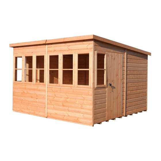
- Page 1 © 10x6 Sun Pent These instructions are for your safety. Please read through them thoroughly before use. PLEASE KEEP THIS LEAFLET FOR FUTURE REFERENCE...
-
Page 2: Table Of Contents
Let’s get started... Important information... Safety Preparation of base Warranty Care, maintenance & Recycling In more detail... Parts List Fascia & Nail List Hardware chart Before you start Detailed Technical Drawing 10-11 Assembly instructions 12-24 For a copy of the instructions or a copy in another language please send an email or write to the address below. -
Page 3: Safety
Safety Check that you have noted all the following instructions: We advise the use of non slip protective gloves throughout the assembly process. We advise the use of steel capped protective footwear throughout the assembly process. We advise that you use a helper to hold the glass in position whilst you nail the beading in place. -
Page 4: Preparation Of Base
Base and Warranty Preparation of base... We recommend that the base onto which your building will stand should be at least 75mm larger in each direction than the total floor size of the building. Actual floor area of the building: 3040mm x 1790mm ... -
Page 5: Care, Maintenance & Recycling
Care, Maintenance and Recycling The 5 golden rules of care: Ensure your base is level and firm. Ensure the building is not sitting directly on the ground using damp proof membrane or the optional timber base. Ensure every piece of timber and surface, especially that is hidden upon assembly is treated with a top quality wood preservative at least twice (before assembly). -
Page 6: Parts List
Stacked Parts List Description (part No ) - Qty... -
Page 7: Fascia & Nail List
Fascia Bag Parts List Description (part No ) - Qty... -
Page 8: Hardware Chart
Nail bag contents Description -- (part No ) - QTY: Hardware Chart Scale 1:1 13mm 8mmFelt Nail (A0023) x 140 16mm Panel Pin (A0024) x128 40mmRound head nail (A0025) x 42 Black 25mm Posi-drive screw (A0031 ) x04 60mmPosi-drive screw (A0035) x81 80mm Posi-drive screw (A0036) x12... -
Page 9: Before You Start
Before you start... Things to check before you start: Ensure your base is ready – See page 4 Check all parts as listed in the parts lists Read the instructions fully before starting work Follow all the health and safety guidelines. When you see the drill icon Only ever drill through the first piece of framework which will be a... -
Page 12: Assembly Instructions
Assembly instructions: These instructions are for your safety. Please read through them thoroughly before use. Treat all the parts before assembly – see page 5! Drill ONE of the A1512 floor panels only at the corner of the framework at the closed end. GB-IE Push the two floor together and screw into place making sure they are flush and true to each other. - Page 13 GB-IE Drill 6 holes in the LH End panel A1513 only The LH Back panel A1766 is positioned first on top oft he Floor A1512 and goes into the corner. Notch to the middle of the back. The cladding overlaps the floor. Push the LH End panel A1766 up to the back panel.
- Page 14 GB-IE Drill 3 holes in the LH Back panel A1766 only The RH Back panel A1766 is pushed up to the other back panel and fixed together, Both the back and front panels fill the entire floor length. 5 mm RH Back Panel (A1766)x01 60mm Screws...
- Page 15 GB-IE Drill 6 holes in the RH End panel A1516 only Drill 3 holes in the LH Front Panel A1765 in the side where the notch is only. Push the RH End panel A516 up to the back and fix as before. The RH Front Panel A1765 goes in front of the side and screws from that panel.
- Page 16 The remaining Front panel A1765 fits in front of the side. GB-IE The front panel is fixed using the holes drilled in the last step. Front Panel (A1765)x01 60mm Screws (A0035)x06 GB-IE Unlock the door and fit the Black Knob set A2888. Black Knob set (A2888)x02 25mm Black Screw...
- Page 17 GB-IE The truss blocks are fitted with the slope towards the back. The front block is fitted 44mm below the notch and the back one 39mm. Drill a hole half way in to the blocks 8mm then through with a 5mm drill. And fix with 80mm screws. Place the truss bars on the top and drill and counter bore as with the blocks and screw into position.
- Page 18 1 Drill one 5mm hole all the way through the roof panel 17mm in from each end of the support frame. Position the Roof A1517 so the support frame sits on top of the ends frame and the slot goes over the GB-IE cladding.
- Page 19 GB-IE Drill and fix the second roof panel as with the previous step. Inside the building, where the roofs meet drill through one sides framework and fix together with 3 screws. 5 mm Roof Panel (A1517) x01 60mm Screws (A0035)x13...
- Page 20 3 Strips of felt have been supplied. Fit the lowest strip first folding the felt over the roof edging, GB-IE at the back then secure with a couple of nails at the top to hold the felt in position nail the sides to the wall with 4 nails each and at the bottom nail at approximately 100mm centres.
- Page 21 GB-IE Fit cover strips at each corner and 4 nails each. 56mm Front cnr Cover strip (A2914) x02 56mm Front ctr Cover strip (A2913) x01 56mm Rear cnr Cover strip (A2912) x02 56mm Rear Cover strip (A2911) x01 40mm Nails (A0025)x24 GB-IE Fix the panels to the floor with 2x60mm screws per panel using the holes previously drilled.
- Page 22 Fit the side fascia's A2916 first so the front edge is flush with the felt at the corner GB-IE Drill and fix the Fascia's with 4 nails each side . Drilling prevents splitting. The two front fascia A2915 fits across the end fascia’s. Drill and fix the Fascia with 3 nails each. The Final A2178 fits over the join in the middle of the front fascia.
- Page 23 The Bench Legs A1772-1 are fitted with the narrow side to the floor. GB-IE The outer pair are pushed up to the front and end walls drill 2 holes at the bottom (into floor bearers) and two at the top inline with the end framework. The middle legs are fitted at the framework in the middle of the front panels with two screws into the floor.
- Page 24 Position the Bench top A1772-2 and screw into position with the holes drilled in the last step. GB-IE Bench Top (A1772-2) x02 60mm Screws (A0035)x12 Push the Safety vents A0476 into the holes in the back panel. GB-IE Safety vent (A0476) x02...
Need help?
Do you have a question about the 10x6 Sun Pent and is the answer not in the manual?
Questions and answers