Table of Contents
Advertisement
Available languages
Available languages
Quick Links
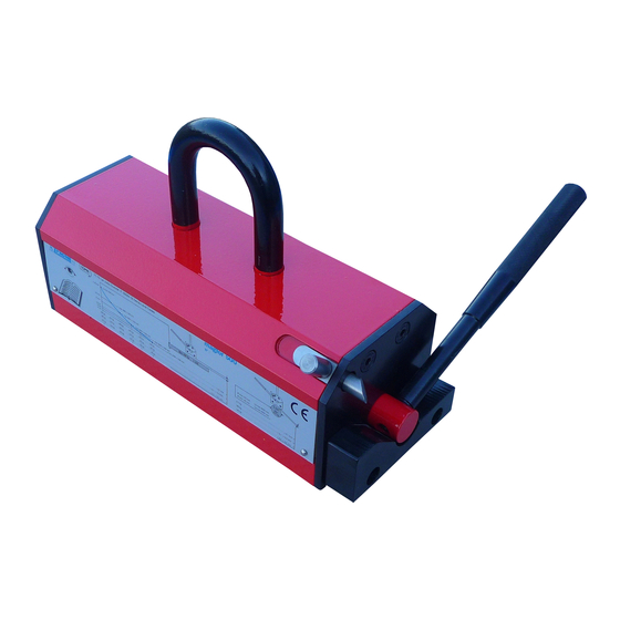
Aimants permanents de levage / Permanent magnet lifters
Sollevatori magnetici / Imanes de elevación permanentes
Lasthebemagnet / Imans de elevação permanentes
Permanente hijsmagneet / Permanentmagnetløfter
DECLARATION DE CONFORMITE
CE*
FR
* NOTICE D'UTILISATION A
L'INTERIEUR
EC DECLARATION OF
GB
CONFORMITY*
* INSTRUCTIONS FOR USE INSIDE
KONFORMITÄTS-Erklärung*
DE
* BETRIEBSANWEISUNG IM
INNEREN
DICHIARAZIONE CONFORMITA
CE*
IT
* ISTRUZIONI D'IMPIEGO
ALL'INTERNO
DECLARACION CE DE
CONFORMIDAD*
ES
* MANUAL DE EMPLEO EN EL
INTERIOR
magfor II
magfor II
PT
NL
NO
PL
DECLARAÇÃO DE CONFORMIDADE*
* INSTRUÇÕES DE UTILIZAÇÃO NO
INTERIOR
EG-VERKLARING VAN
OVEREENSTEMMING*
* GEBRUIKSAANWIJZING
SAMSVARSERKLÆRING*
* BRUKERHÅNDBOK
DEKLARACJA ZGODNOŚCI WE*
* INSTRUKCJA UŻYTKOWANIA
WEWNĄTRZ
p. 1 / 96
Advertisement
Table of Contents

Related Manuals for Tractel magfor II


Summary of Contents for Tractel magfor II
- Page 1 II Aimants permanents de levage / Permanent magnet lifters Sollevatori magnetici / Imanes de elevación permanentes Lasthebemagnet / Imans de elevação permanentes Permanente hijsmagneet / Permanentmagnetløfter magfor II DECLARATION DE CONFORMITE DECLARAÇÃO DE CONFORMIDADE* * INSTRUÇÕES DE UTILIZAÇÃO NO * NOTICE D’UTILISATION A...
- Page 2 Dyrektywy nr 2006/42/WE w zakresie bezpieczeństwa i higieny pracy. Osoba upoważniona do podpisu przez deklarującego, Dyrektor: Emmanuel TRIPIER Directeur des Opérations dûment mandaté Tractel Solutions SAS 77-79 rue Jules Guesde Etiquette 69230 St Genis Laval Cedex Tel +33 4 78 50 18 18 / Fax +33 4 72 66 25 41 info.tractelsolutions@tractel.com...
- Page 3 II Aimants permanents de levage / Permanent magnet lifters Sollevatori magnetici / Imanes de elevación permanentes Lasthebemagnet / Imans de elevação permanentes Permanente hijsmagneet / Permanentmagnetløfter magfor II NOTICE MANUAL DE D’UTILISATION UTILIZAÇÃO INSTRUCTIONS FOR GEBRUIKSAANWIJ ZING GEBRAUCHSANWEIS BRUKERHÅNDBOK...
-
Page 4: Table Of Contents
Français ................................7 CONSIGNES PRIORITAIRES ........................7 PRESENTATION ET DESCRIPTION DE L’APPAREIL ................8 SPECIFICATIONS TECHNIQUES ET DIMENSIONNELLES ..............9 FACTEURS INFLUANT SUR LA CAPACITÉ DE LEVAGE................9 MODE OPERATOIRE ..........................13 CONTRE-INDICATIONS D’EMPLOI ......................14 VERIFICATION REGLEMENTAIRES OBLIGATOIRES ................15 STOCKAGE ET ENTRETIEN DU MATERIEL ................... - Page 5 SAV/ AFTER SALES ............................91 LISTE PIECES DETACHEES/ SPARE PARTS LIST ................. 91 REMPLACEMENT DU SYSTEME DE SECURITE D’UN AIMANT DE LEVAGE MAGFOR II ....92 REPLACEMENTOF A SAFETY LOCKING SYSTEM ON A MAGFOR II MAGNET LIFTER ...... 92 NOTES ................................93 M 6053 M rev 14 –...
- Page 6 Langue d’origine / Language of origin / Idioma de origen / Lingua di origine / Ursprungssprache / Lingua de origem / kildesprog / Brontaal / Jezyk oryginalu / kilde språk / källspråk Anglais / English / Inglés / Inglese / Englisch / Inglês / Engels / Angielski / engelsk / engelska Coefficient d’épreuve statique / Static test coefficient / Coeficiente de prueba estática / Statische Prüfungsfaktor / Coeficiente de teste estático / Statisk test koefficient / Statische test coëfficient / Wspolczynnik testu statycznego / Statisk test faktor / Testikuorma...
-
Page 7: Français
(voir paragraphes « spécifications techniques et dimensionnelles »). ƒ Toujours travailler dans l’axe de l’anneau des aimants de levage magfor II, ne jamais tirer avec un angle par rapport à la verticale. ƒ... -
Page 8: Presentation Et Description De L'appareil
Mise en service Avant la première utilisation, monter le levier (4) sur l’axe du rotor (6). Deux cas de montages possibles suivant les modèles d’aimants magfor II: ƒ Cas 1 : visser le levier (4) dans le trou fileté de l’axe du rotor (6). -
Page 9: Specifications Techniques Et Dimensionnelles
230 +/- 20 *CMU: Capacité maximale d’utilisation + : D & E ne sont pas cotés de la même manière pour magfor II Les capacités spécifiées sont données pour de l’acier à faible teneur en carbone (tel que le S235) avec un état de surface présentant une rugosité... - Page 10 à la surface des pôles actifs. Il est donc nécessaire de rechercher, par un placement judicieux de l’aimant, la meilleure horizontalité de la charge. Nature de la charge CMU* (kg) magfor II magfor II magfor II magfor II magfor II...
- Page 11 Tableaux pratiques de la réduction de capacité Détermination capacité aimants permanents magfor II dans le cas de pièces plates en acier S235. Surface rectifiée, Surface laminée à chaud/rouillée Surface irrégulière et rugueuse L min propre et lisse. Entrefer 0,1 à 0,3 mm Entrefer 0,3 à...
- Page 12 Détermination de la capacité des aimants permanents magfor II dans le cas de pièces cylindriques en acier S235. Attention, les magfor II TP pour tôles minces ne sont pas conçus pour la manutention des ronds. Ø Entrefer Entrefer Entrefer < 0,1 mm 0,1 à...
-
Page 13: Mode Operatoire
2. Avant la première utilisation, monter le levier (4) sur l’axe du rotor (6). Deux cas de montages possibles suivant les modèles d’aimants magfor II : a. Cas 1 : visser le levier (4) dans le trou fileté de l’axe du rotor (6). -
Page 14: Contre-Indications D'emploi
ƒ ƒ La température de la charge ou de l’environnement doit être comprise entre –20 et +80°C. (- 20 et +250°C pour les magfor II HT) ƒ Ne pas soulever de matière dangereuse, explosive ou radioactive. Ne pas soulever de charges sur lesquelles seraient posées d’autres charges non solidaires. -
Page 15: Verification Reglementaires Obligatoires
Vérification annuelles art 24 du décret du 1er mars 2004 ƒ Les aimants de levage magfor II utilisés dans un établissement visé à l’article L.231-1 du code du travail, doivent, conformément à l’article R. 233-11 dudit code, être soumis tous les douze mois à une vérification périodique comportant un examen ayant pour objet de déceler toute détérioration, ou autre limite d’emploi, susceptible d’être à... -
Page 16: Stockage Et Entretien Du Materiel
ƒ Tout matériel déformé doit être immédiatement retiré du service. ƒ En cas de doute, TRACTEL SOLUTIONS vous propose expertise et devis gratuits en ses ateliers. TRACTEL SOLUTIONS SAS décline toute responsabilité pour les conséquences d’un démontage ou d’une modification apportée hors de son contrôle. Spécialement en cas de remplacement de pièces d’origine par des pièces d’une autre provenance. -
Page 17: English
II. PRIORITY INSTRUCTIONS Before using the magfor II magnet lifter, it is essential that this manual be read and fully understood and that all the instructions be followed. This manual should be made available to every operator. Extra copies of this manual can be supplied on request. -
Page 18: Presentation And Description Of Equipment
PRESENTATION AND DESCRIPTION OF EQUIPMENT Functioning The magnetic force generated by the permanent magnet lifters is, « activated » or « deactivated » depending on the position of the rotor. When activated, the magnetic force creates an attraction between the active poles of the magnet lifter and the load, holding the latter in place. This attraction force depends on the load (contact surface with active poles and its thickness) but also on its magnetic performance (iron content) and its surface quality (creation of an air-gap). - Page 19 II (100 – 300 – 500 – 1000 – 2000 – 3000 - 5000) WLL* WLL* Weight Ø Temperature on plate on round Type Group code maxi (°C) (kg) (mm) magfor II 100 185438 130 +/- 5 75 +/- 5...
-
Page 20: Influential Factors On Lifting Capacity
That is why it is necessary to find out, with a good positioning of the magnet lifter, the best horizontal position of the load before lifting. Kind of load WLL (kg) magfor II magfor II magfor II magfor II... - Page 21 Practical tables for capacity reduction Determination of permanent magnet lifters magfor II capacity in case of S235 steel plates. Ground, clean & smooth surface Hot rolled, rusty surface Irregular and rough surface L min Air gap < 0,1 mm Air gap 0,1 to 0,3 mm...
- Page 22 Determination of permanent magnet lifters magfor II capacity in case of S235 steel round surface. Please note, magfor II TP for thin plates are not designed for handling rounds. Ø Air-gap Air-gap Air-gap < 0,1 mm 0,1 to 0,3mm 0,3 to 0,5mm Ø...
-
Page 23: Operating Instructions
Do not hesitate to make several trial lifts at low level in order to control the balance of the load. 6. Control that constraints are on the axle of the magfor II magnet lifter : never apply inclined loads. -
Page 24: Warning Against Hazardous Operations
Never leave a load unsupervised. ƒ Temperature of the load or/ and atmosphere must be between –20 and +80°C. (-20 to +250°C for magfor II HT) ƒ Never lift dangerous, explosive or radioactive loads. Never lift loads which have non-attached charges on top. -
Page 25: Material Control And Checking
MATERIAL CONTROL AND CHECKING Before each use Read and respect all conditions given by the magnet instructions for use. ƒ ƒ Visually inspect all parts of magnet lifter. ƒ Carefully clean active poles (contact with the load) and if necessary, suppress spotting out and flashes with a soft file. -
Page 26: Storage And Maintenance Instructions
Any deformed equipment must be immediately replaced. ƒ In case of any doubt, TRACTEL SOLUTIONS SAS can offer advice and repair service. TRACTEL SOLUTIONS SAS declines all responsibility for the consequences of dismantling or altering the machine by any unauthorized person. Specially excluded is the replacement of original parts by parts of another manufacturer. -
Page 27: Italiano
Italiano Al fine di assicurare il miglioramento continuo dei propri prodotti, TRACTEL si riserva il diritto d’apportare tutte le modifiche del caso ai materiali descritti nelle presenti istruzioni. Queste istruzioni di uso e manutenzione contengono tutte le indicazioni per un utilizzo ottimale e sicuro dei sollevatori magnetici magfor II. -
Page 28: Descrizione Dell'apparecchio
5. Etichetta 6. Asse del rotore Messa in servizio Al primo utilizzo, montare la leva (4) sull’asse del rotore (6). Secondo i tipi di magfor II, sono possibili due sistemi di montaggio : ƒ Caso 1 : avvitare la leva (4) nel foro filettato dell’asse del rotore (6). -
Page 29: Specifiche Tecniche
IMPORTANTE : la portata massima di utilizzo, indicata sul sollevatore magnetico, corrisponde alle condizioni qui sopra indicate, sarà quindi ridotta per altre condizioni (vedi paragrafi seguenti). magfor II (100 – 300 – 500 – 1000 – 2000 – 3000 - 5000) WLL*... - Page 30 La potenza massima del magnete è ottenuta quando le forze si applicano perpendicolarmente alla superficie dei poli attivi. E’ quindi necessario ricercare, per un corretto posizionamento del magnete, la migliore orizzontalità del carico. Natura del carico CMU in (kg) magfor II magfor II magfor II magfor II magfor II...
- Page 31 Tabelle delle riduzioni di portata Determinazione della portata dei magneti permanenti magfor II nel caso di pezzi in acciaio S235. Superficie del terreno, pulita e liscia Superficie laminate a caldo, arrugginito Superficie irregolare e ruvida L min Traferro < 0,1 mm...
- Page 32 Determinazione della portata dei magneti permanenti magfor II in caso di pezzi cilindrici in acciaio S235. Si prega di notare, magfor II TP per lastre sottili non sono progettati per la movimentazione di barre tonde. Ø traferro traferro traferro < 0,1 mm...
-
Page 33: Modalita' D'impiego
1. Prima di utilizzare il magnete, leggete attentamente e completamente le istruzioni. 2. Al primo utilizzo, montare la leva (4) sull’asse del rotore (6). Esistono due tipi di monatggio per i modelli di magneti magfor II: a. Caso 1: avvitare la leva (4) nel foro filettato dell’asse del rotore (6). -
Page 34: Controindicazioni All'uso
ƒ Non lasciare mai senza sorveglianza un carico sospeso. ƒ La temperatura del carico o dell’ambiente deve essere compresa tra –20 e +80°C. (-20 e +250°C per magfor II HT) ƒ Non sollevare materiali pericolosi, esplosivi o radioattivi. ƒ Non sollevare dei carichi sui quali siano posati altri carichi non accuratamente fissati. -
Page 35: Verifiche Obbligatorie
Verifiche annuali ƒ I sollevatori magnetici magfor II, prendendo spunto dalla normativa francese (art. L.231-1 e R. 233-11 del codice del lavoro), devono essere sottoposti ogni dodici mesi ad una verifica che comporti una serie di controlli, aventi come obiettivo quello di trovare ogni possibile deterioramento, o altri impedimenti, che possano dar origine a situazioni pericolose. -
Page 36: Español
Español Con el fin de garantizar la constante mejora de sus productos, TRACTEL SOLUTIONS S.A.S se reserva el derecho de efectuar cualquier modificación que considere oportuna en los materiales descritos en este manual. Este manual contiene todas las instrucciones necesarias para un uso óptimo y seguro de los imanes de elevación magfor II. -
Page 37: Presentación Y Descripción Del Aparato
Antes de la primera utilización, colocar la palanca (4) en el eje del rotor (6). Existen dos posibilidades para el montage según sea el modelo de imán magfor II: Caso 1: apretar la palanca (4) en el orificio roscado del eje del rotor (6). -
Page 38: Características Técnicas Y Dimensiones
IMPORTANTE: la capacidad máxima de utilización indicada en el imán, correspondiente a las condiciones descritas anteriormente, se reducirán si no se respetan dichas condiciones (ver apartados siguientes ). magfor II (100 – 300 – 500 – 1000 – 2000 – 3000 - 5000) WLL* WLL*... -
Page 39: Factores Que Influyen Sobre La Capacidad De Elevación
La capacidad máxima del imán se obtiene cuando las fuerzas se aplican perpendicularmente a la superficie de los polos activos. Entonces es necesario buscar, mediante la ubicación del imán, la mejor horizontalidad de la carga. Naturaleza de la carga CMU (kg) magfor II magfor II magfor II magfor II magfor II... - Page 40 Tablas prácticas de la reducción de capacidad Determinación de la capacidad de los imanes permanentes magfor II en el caso de piezas rectangulares en acero S235. Superficie lisa y limpio Superficie laminada en caliente, oxidado Superficie irregular y rugosa L min Entrehierro <...
- Page 41 Determinación de la capacidad de los imanes permanentes magfor II en el caso de piezas rundas en acero S235. Tenga en cuenta, magfor II TP para placas delgadas no están diseñados para el manejo de barras redondas.. Ø D entrehierro...
-
Page 42: Instrucciones Para El Funcionamiento
2. Antes de la primera utilización, colocar la palanca (4) en el eje del rotor (6). Existen dos posibilidades para el montaje según sea el modelo de imán magfor II: Caso 1: apretar la palanca (4) en el orificio roscado del eje del rotor (6). -
Page 43: Operaciones No Aconsejables
No dejar jamás una carga suspendida sin vigilancia. ƒ La temperatura de la carga o del ambiente debe estar comprendida entre –20°C y +80°C. (-20 y +250°C para magfor II HT) ƒ No elevar materiales peligrosos, explosivos o radioactivos. ƒ... -
Page 44: Revisiones Periódicas Obligatorias
Comprobar el funcionamiento de la palanca y del sistema de cierre. Revisiones anuales ƒ Los imanes de elevación magfor II deben revisarse cada doce meses, deben pasar un examen el objeto del cual es descubrir cualquier deterioro, u otro límite de uso, susceptible de ser el origen de situaciones peligrosas. -
Page 45: Deutsch
Die Anweisung muss dem Anwender jederzeit verfügbar sein. Weitere Exemplare werden auf Anfrage geliefert. Die Lasthebemagnete magfor II dienen dem sicheren Heben von Lasten. Sie dürfen nur von ƒ Personen benutzt werden, die mit den Geräten vertraut sind und diese Anweisungen gewissenhaft befolgen. -
Page 46: Gerätebeschreibung
5. Typen- und Hinweisschild 6. Rotoraxe Einsatzbereitschaft Vor der ersten Benutzung den Gerätehebel (4) auf die Rotoraxe (6) montieren. Je nach magfor II Typ gibt es folgende zwei Möglichkeiten: ƒ Typ 1: Hebel (4) in die Gewindebohrung der Rotoraxe (6) schrauben. -
Page 47: Technische Daten
WICHTIG: Die auf dem Typenschild angegebene nominelle Tragfähigkeit bezieht sich auf den oben beschriebenen Idealfall. Bei abweichenden Bedingungen reduzier sie sich entsprechend (siehe nachfolgende Abschnitte). magfor II (100 – 300 – 500 – 1000 – 2000 – 3000 - 5000) T* bei T* bei... - Page 48 Oberfläche). Das gleiche prozentuale Reduktion von WLL gelten magfor in dieser Tabelle nicht aufgeführt. Tabellen über reduzierte Tragfähigkeit Bestimmung der Tragfähigkeit eines magfor II Lasthebemagnets bei Stahlblech S235. M 6053 M rev 14 – 02/2018 p. 48 / 96...
- Page 49 Std & HO Std & HO Std & HO ≥ 15 ≥ 10 magfor II 100 ≥ 6 magfor II 100 HO ≥ 4 ≥ 2 ≥ 25 magfor II 180 TP ≥ 15 magfor II 200 HT ≥ 10 magfor II 300 ≥...
- Page 50 Bestimmung der Tragfähigkeit eines magfor II Lasthebemagnets bei Rundmaterial aus S235. Bitte beachten Sie, magfor II TP für dünne Platten nicht für den Umgang mit Rundstäbe ausgelegt. Ø D Luftspalt Luftspalt Luftspalt < 0,1 mm 0,1-0,3mm 0,3-0,5mm Ø D min Ø...
-
Page 51: Gebrauchsanweisung
Gerät über Tragfähigkeit). Sicherheitseinrichtung Die Hebelsperre (3) der Lasthebemagnete magfor II sichert den Hebel (4) automatisch und verhindert eine versehentliche Entmagnetisierung während des Hebens. Zum Entmagnetisieren ist eine „Zwei-Hand-Bedienung“ erforderlich. M 6053 M rev 14 – 02/2018 p. 51 / 96... -
Page 52: Nicht-Bestimmungsgemässer Einsatz
ƒ Nie eine hängende Last ohne Aufsicht lassen. ƒ Zulässiger Temperaturbereich für Last und Umgebung: -20°C bis +80°C. (-20 bis +250°C für magfor II HT) ƒ Keine gefährlichen, explosiven oder radioaktiven Lasten Heben. ƒ Nie Lasten heben, auf denen sich lose Teile befinden. -
Page 53: Vorgeschrieben Sicherheitskontrollen
Feile entfernen. Gerät nicht benutzen, wenn die Pole beschädigt sind. Funktion des Hebels und der Hebelsperre prüfen. ƒ Jährliche Prüfung gemäß einschlägiger Vorschrift(en) magfor II Lasthebemagnet müssen mindestens einmal auf ihre Betriebssicherheit ƒ überprüft werden. ƒ Gerät auf Verformungen, Risse oder andere Fehler prüfen. Wenn die Halteöse eine Abnutzung von mehr als 10% aufweist, muss sie ersetzt werden. -
Page 54: Português
Português Afim de garantir a constante melhoria dos seus produtos, A TRACTEL SOLUTIONS, S.A.S reserva o direito de efectuar qualquer modificação que considere oportuna nos materiais descritos neste manual. Este manual contem todas as instruções necessárias para uma boa e segura utilização dos imans de elevação magfor II. -
Page 55: Apresentação E Descrição Do Aparelho
Antes da primeira utilização, colocar a alavanca (4) no eixo do rotor (6). Existem duas possibilidades para a montagem, dependendo do modelo do íman magfor II: Caso 1: Apertar a alavanca (4) no orifício roscado do eixo do rotor (6). -
Page 56: Especificações Técnicas E Dimensões
IMPORTANTE : A capacidade máxima de utilização indicada no íman, correspondente às condições descritas anteriormente, esta será reduzida se não se respeitarem as condições (ver os parágrafos seguintes). magfor II (100 – 300 – 500 – 1000 – 2000 – 3000 - 5000) WLL* WLL*... -
Page 57: Factores Influentes Na Capacidade De Elevação
A capacidade máxima do íman obtém-se quando as forças se aplicam perpendicularmente à superfície dos pólos activos. Portanto é necessário encontrar, através de um bom posicionamento do íman, a melhor horizontalidade da carga. Natureza da carga CMU (kg) magfor II magfor II magfor II magfor II magfor II... - Page 58 Quadros práticos da redução de capacidade Determinação capacidade imans permanentes magfor II no caso de placas em aço S235 Superficie do solo, limpo e liso Laminado a quente, enferrujado Superficie irregular e aspera L min Entreferro < 0,1 mm Entreferro 0,1 - 0,3 mm...
- Page 59 Determinação da capacidade dos imans permanentes magfor II no caso de peças cilíndricas em aço S235 Por favor note, magfor II TP para placas finas não são projetados para lidar com barras redondas. Ø entreferro entreferro entreferro < 0,1 mm...
-
Page 60: Modo De Funcionamento
2. Antes da primeira utilização, colocar a alavanca (4) no eixo do rotor (6). Existem duas possibilidades para a montagem, dependendo do modelo do íman magfor II: a. Caso 1 : Apertar a alavanca (4) no orifício roscado do eixo do rotor (6). -
Page 61: Contra-Indicações De Utilização
ƒ Nunca deixar a carga suspensa sem vigilância. ƒ A temperatura da carga ou do ambiente deve estar compreendida entre –20 e +80ºC. (-20 e +250°C para magfor II HT) ƒ Não elevar materiais perigosos, explosivos ou radioactivos. ƒ Não elevar cargas sobre as quais se coloquem outras cargas não lingadas. -
Page 62: Revisões Periódicas Obrigatórias
Verificações anuais art. 24 do Decreto de 01/03/2004 ƒ Os imans de elevação magfor II utilizados num local a que diga respeito o artigo L231-1 do código do trabalho, devem, conforme o artigo R. 233-11, ser revistos a cada doze meses, devem passar por um exame cujo objectivo é descobrir qualquer deteorização, ou outra limitação de uso, susceptível de originar situações perigosas. -
Page 63: Nederlands
Nederlands Technische wijzigingen voorbehouden. Deze handleiding bevat alle informatie voor een optimaal en veilig gebruik van de magfor II hijsmagneet. VEILIGHEIDSADVIEZEN Voor ieder gebruik van een magfor II-hijsmagneet moet deze handleiding gelezen en begrepen zijn. De handleiding moet voor de gebruiker te allen tijde beschikbaar zijn. Meer exemplaren worden op aanvraag geleverd. -
Page 64: Apparaat Beschrijving
APPARAAT BESCHRIJVING Funktiebeschrijving Het door de magfor II hijsmagneet opgewekte magnetische veld werkt op de te hijsen last met ijzerhoudende materialen of is in het apparaat kort gesloten, afhankelijk van de positie van de bedieningshandel. Deze staat of in de positie magneet „GEACTIVEERD“ of „GEDEACTIVEERD“. -
Page 65: Technische Gegevens
BELANGRIJK: De op het typeplaatje aangegeven nominale capaciteit heeft betrekking op de hierboven beschreven ideale situatie. Bij afwijkende condities vermindert deze zich navenant (zie de volgende paragraaf). magfor II (100 – 300 – 500 – 1000 – 2000 – 3000 - 5000) WLL* WLL*... -
Page 66: Factoren, Die Van Invloed Zijn Op De Hijscapaciteit
Daarom moet u zorgvuldig uitvinden, waar de hijsmagneet op de last geplaatst moet worden, zodat de last zo horizontaal mogelijk gehesen kan worden. Materiaalsoort Maximale capaciteit (kg) magfor II magfor II magfor II magfor II... - Page 67 Tabel met capaciteitsreductie Bepalen van de capaciteit van een magfor II hijsmagneet Hijsmagneet bij staal platen S235. Grondoppervlak, schoon en glad Gelamineerd warm of roestige Onregelmatig of ruw oppervlak L min Luchtspleet < 0,1 mm Luchtspleet 0,1 tot 0,3 mm...
- Page 68 Bepalen van de capaciteit van een magfor II hijsmagneet bij rond materiaal uit S235. Let op, magfor II TP voor dunne platen zijn niet ontworpen voor het verwerken van ronde staven. Ø Luchtspleet Luchtspleet Luchtspleet < 0,1 mm 0,1-0,3mm 0,3-0,5mm Ø...
-
Page 69: Gebruiksaanwijzing
300 kg capaciteit). Veiligheidsvoorziening De grendelpal (3) van de hijsmagneet magfor II zekert de bedieningshandel (4) automatisch en voorkomt een ongewenste DEACTIVERING van de magneet tijdens het hijsen. Voor het DEACTIVEREN van de magneet is een „Twee Handen Bediening“ vereist. -
Page 70: Niet Toegestaan Gebruik
ƒ Nooit een gehesen last zonder toezicht laten hangen. ƒ Toegestaan temperatuurbereik voor last en omgeving: -20 tot +80 °C. (-20 tot +250°C voor magfor II HT) ƒ Geen gevaarlijke, explosieve of radioactieve lasten hijsen. ƒ Nooit lasten hijsen, waarop zich losse delen bevinden. -
Page 71: Voorgeschreven Veiligheidscontrole
Het apparaat niet gebruiken, als de polen beschadigd zijn. Functie van de bedieningshandel en de vergrendelingspal controleren. ƒ Jaarlijkse controle volgens lokaal geldende voorschrift(en) magfor II hijsmagneten moeten tenminste eenmaal op hun bedrijfszekerheid getest ƒ worden. ƒ... -
Page 72: Norsk
VIKTIG INFORMASJON Før magfor II magnetløfter tas i bruk, er det viktig at denne håndboken blir lest og forstått, og at alle instrukser blir fulgt. Håndboken skal være tilgjengelig for alle brukere. Flere eksemplarer kan skaffes til veie på... -
Page 73: Beskrivelse Av Utstyret
BESKRIVELSE AV UTSTYRET Funksjonsmåte Magnetisk kraft genereres fra innebygde permanent-magneter, og kan aktiveres eller deaktiveres ved hjelp av en roterende mekanisme. I aktivert stilling vil magnetkreftene generere en tiltrekningskraft mellom de aktive polene til magnetløfteren og lasten, derved holdes lasten fast. Denne tiltrekningskraften avhenger av lasten (kontaktflaten mot de aktive polene såvel som godstykkelsen), også... -
Page 74: Tekniske Spesifikasjoner
VIKTIG: Tillatt arbeidslast (WWL) som oppgitt på magnetløfteren gjelder bare under de forhold som er oppgitt ovenfor. Tillatt arbeidslast må reduseres dersom disse kravene ikke oppfylles (se etterfølgende avsnitt). magfor II (100 – 300 – 500 – 1000 – 2000 – 3000 - 5000) WLL* WLL*... -
Page 75: Faktorer Som Påvirker Løftekapasiteten
For å få den maksimale løftekapasiteten fra magnetløfteren, må vekten av lasten virke vinkelrett på flaten til de aktive polene. Det er derfor nødvendig å finne ut på forhånd hva som er beste plasseringssted på lasten. Lasttype WLL (kg) magfor II magfor II magfor II magfor II magfor II... - Page 76 Std & HO Std & HO Std & HO ≥ 15 ≥ 10 magfor II 100 ≥ 6 magfor II 100 HO ≥ 4 ≥ 2 ≥ 25 magfor II 180 TP ≥ 15 magfor II 200 HT ≥ 10 magfor II 300 ≥...
- Page 77 Løftekapasitet for magfor II magnetløfter gjeldende for runde emner av material-kvalitet S235. Vær oppmerksom på, magfor II TP for tynne platene ikke er designet for å håndtere runde barer. Ø D Klaring Klaring Klaring < 0,1 mm 0,1 til 0,3 mm 0,3 til 0,5 mm Ø...
-
Page 78: Bruksmåte
300 kg kapasitet, opp til 20 kg for en magnetløfter med kapasitet større enn 300 kg). Sikkerhetssperre Magnetløfteren magfor II er utstyrt med en sikkerhetssperre på håndtaket som forhindrer utilsiktet deaktivering. Det er nødvendig å bruke to hender ved deaktivering. M 6053 M rev 14 –... -
Page 79: Advarsel Mot Farlig Bruk
ƒ La aldri en last bli hengende. Lastens temperatur eller lufttemperaturen må være mellom –20 og +80° C. (-20 og +250°C i ƒ magfor II HT) ƒ Løft aldri farlig, eksplosiv eller radioaktiv last ƒ Løft aldri en last som har løse gjenstander liggende på topp Overskrid aldri vektbegrensningene eller maks/ min-dimensjonene som angitt i kap. -
Page 80: Obligatoriske Kontrollpunkter
Årlige kontroller i henhold til artikkel 24 i direktiv av 01/03/2004 ƒ En magfor II magnetløfter som brukes i industriell virksomhet er underlagt artikkel L.231-1 i arbeidsdirektivet. Den skal kontrolleres hvert år i henhold til artikkel R. 233- 11. Årlig kontroll skal omfatte alle nødvendige inspeksjoner for å avdekke skader eller potensielle problemer som kan forårsake farlige situasjoner. -
Page 81: Polski
Instrukcja powinna być udostępniona każdemu z operatorów. Na życzenie zapewniamy dodatkowe kopie niniejszej instrukcji. Uchwyty z magnesem trwałym magfor i magfor II umożliwiają operatorowi w pełni bezpieczną ƒ pracę. Należy upewnić się, że urządzenie jest obsługiwane oraz podwieszane wyłącznie przez operatora przeszkolonego w zakresie właściwej obsługi. -
Page 82: Prezentacja I Opis Urządzenia
PREZENTACJA I OPIS URZĄDZENIA Działanie Pole magnetyczne generowane przez magnes trwały w uchwycie jest „włączane” i „wyłączane”, zależnie od pozycji wirnika. Po aktywacji, oddziaływanie pola magnetycznego wytarza przyciąganie pomiędzy aktywnymi biegunami uchwytu a ładunkiem – utrzymując go na miejscu. Siła przyciągania zależy od ładunku (materiał i grubość powierzchni styku z biegunami aktywnymi), w tym jego magnetyczności (zawartość... -
Page 83: Dane Techniczne
Udźwig* i wymiary WAŻNE: dopuszczalne obciążenie robocze uchwytu magnetycznego odpowiadające wyżej opisanym warunkom musi zostać zredukowane w przypadku niezachowania opisanych warunków (patrz niżej). magfor II (100 – 300 – 500 – 1000 – 2000 – 3000 - 5000) DOR* DOR*... -
Page 84: Czynniki Wpływające Na Udźwig
W celu osiągnięcia maksymalnego udźwigu uchwytu, ładunki powinny być prostopadłe do powierzchni biegunów aktywnych. Z tego powodu, należy przed podnoszeniem odnaleźć najbardziej poziomą pozycję ładunku właściwie ustawiając uchwyt magnetyczny. Typ ładunku DOR (kg) magfor II magfor II magfor II magfor II magfor II... - Page 85 Praktyczne tabele redukcji udźwigu Określenie udźwigu uchwytów magnetycznych magfor i magfor II dla blachy ze stali S235. Powierzchnia szorstka i Gładka i czysta Powierzchnia walcowana nieregularna powierzchnia na gorąco, zardzewiała Szczelina 0,3 do 0,5 Szczelina < 0,1 mm Szczelina 0,1 do 0,3 mm...
- Page 86 Określenie udźwigu uchwytów magnetycznych magfor i magfor II dla okrągłych powierzchni ze stali S235. Uchwyt magfor II TP do blach cienkich nie jest przeznaczony do pracy z powierzchniami okrągłymi. Ø D Szczelina Szczelina Szczelina < 0,1 mm 0,1 do 0,3 mm 0,3 do 0,5 mm Ø...
-
Page 87: Instrukcja Użytkowania
Nałóż uchwyt magnetyczny na ładunek, umieść go tak, aby zachować równowagę podczas podnoszenia. W celu kontroli równowagi można wykonać kilka prób podnoszenia na niewielką wysokość. Obciążenia należy podwieszać w osi uchwytów magnetycznych magfor II: nie obciążać pod kątem. W celu aktywacji uchwytu magnetycznego pociągnij za dźwignię (4) i przekręć do blokady (3). -
Page 88: Ostrzeżenia Przed Niebezpiecznymi Działaniami
OSTRZEŻENIA PRZED NIEBEZPIECZNYMI DZIAŁANIAMI ƒ Pod żadnym pozorem nie należy aktywować ani dezaktywować uchwytu magnetycznego, jeśli grubość ładunku nie odpowiada wartościom określonym w „praktycznych tabelach redukcji udźwigu” lub na tabliczce znamionowej. ƒ Nigdy nie należy puszczać dźwigni wolno. Dźwignię należy utrzymywać do chwili osiągnięcia pozycji początkowej. -
Page 89: Kontrola Materiału
KONTROLA MATERIAŁU Przed każdym użyciem Zapoznaj się i przestrzegaj warunków instrukcji użytkowania uchwytu. ƒ ƒ Dokonaj wizualnej kontroli wszystkich elementów uchwytu magnetycznego. ƒ Dokładnie oczyść bieguny aktywne (miejsce kontaktu z ładunkiem) i, jeśli to konieczne, usuń nierówności miękkim pilnikiem. Nie używaj uchwytu z wadami powierzchni biegunów aktywnych. -
Page 90: Przechowywanie I Konserwacja
Uszkodzone części należy wymienić na oryginalne części zamienne TRACTEL SOLUTIONS (patrz załącznik). ƒ Urządzenia wykazujące ślady odkształceń należy natychmiast wymienić. W przypadku wątpliwości, zwrócić się do TRACTEL SOLUTIONS SAS po poradę lub ƒ naprawę. TRACTEL SOLUTIONS SAS nie przyjmuje odpowiedzialności za konsekwencje demontażu urządzeń... -
Page 91: Sav/ After Sales
FR-GB SAV/ AFTER SALES LISTE PIECES DETACHEES/ SPARE PARTS LIST magfor II 100 magfor II 300 magfor II 500 magfor II 1000 magfor II 2000 magfor3000 N° MAG100-PG MAG300-PG MAG500- MAG1000-PG MAG2000-PG MAG3000-PG 99PG MAG100-2 MAG300-2 MAG500-2 MAG1000-2 MAG2000-2 MAG3000-2... -
Page 92: Remplacement Du Systeme De Securite D'un Aimant De Levage Magfor Ii
5. Placer le nouveau système de sécurité fourni par TRACTEL SOLUTIONS SAS à la place de l’ancien et dans la même position. Lors du montage, ajouter un peu de graisse et vérifier que le système coulisse bien. -
Page 93: Notes
NOTES ..................................................................................................................................................................................................................................................................................................................................................................................................................................................................................................................................M 6053 M rev 14 – 02/2018 p. 93 / 96... - Page 94 NOTES ....................................................................................................................................................................................................................................................................................................................................................................................................................................................................................................................................................M 6053 M rev 14 – 02/2018 p. 94 / 96...
- Page 95 Nom de l’utilisateur Date de mise en service Name of user Date of first use Nome dell’utilizzatore Data di messa in servizio Nombre del usuario Fecha de puesta en servicio Name des Benutzers Datum der Inbetriebnahme Naam van de gebruiker Datum Ingebruikneming Nome do utilizador Data da primeira utilização...
- Page 96 Fax: +49 22 02 10 04 70 infoit@tractel.com Phone: +33 3 25 21 07 00 tractel.mexico@tractel.com info.greifzug@tractel.com Fax: +33 3 25 21 07 11 NL B DK L - Tractel Benelux BV info.tsas@tractel.com E - Tractel Iberica S.A. Paardeweide 38 Carretera del Medio, 265 Breda 4824 L’Hospitalet...
Need help?
Do you have a question about the magfor II and is the answer not in the manual?
Questions and answers