Table of Contents
Advertisement
Advertisement
Table of Contents

Related Manuals for Navman Qube4


Summary of Contents for Navman Qube4
- Page 1 #090 Installation Training & Troubleshooting • Qube4 • M-Nav800 Rev. 05302013...
-
Page 2: Table Of Contents
Fleet Tracking & Management ………..….……………..……….……… Page 3 Recommended Installation Practices ….……………..……….……… Page 4 Recommended Tools and Supplies …….……………….………………. Page 5 Qube4 Hardware …….…………………….……………………………………. Pages 6-10 Identifying Correct Wires ……………..….………………………….…….. Pages 11-12 “Poke & Wrap” Solder-less Connections ………….…………………. Page 13 Chassis Ground Connection …………………………….…………….……... -
Page 3: Fleet Tracking & Management
Fleet Tracking and Management Global Positioning Mobile iAVL Online AVL2 System Satellites Cellular Network (SMS) Qube4 – ATT Qube Fleet Navman Wireless Operations Center Qtanium Fleet 3 | Confidential... -
Page 4: Recommended Installation Practices
Recommended Installation Practices Review this installation manual to become familiar with all installation procedures and electrical wiring requirements prior to starting the installation. This installation guide has been prepared to provide you with details necessary to complete the Qube installation. Use of proper tools and testing equipment is required. -
Page 5: Recommended Tools And Supplies
• Panel Removal Tool Electrical Tape • • Digital Multimeter (DMM) Spare Fuses (3 Amp) • • T-10S Torx Screwdriver Self-Tapping Screws (for Qube4) T-10S Torx Screwdriver Recommended Tool: Tamper Proof Gardner Bender (required for Qube4) GS-394 5 | Confidential... -
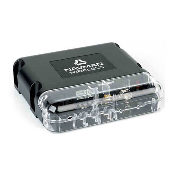
Page 6: Qube4 Hardware
Qube4 Hardware To allow for quicker and easier installations, Navman To ensure professional installation, Navman Wireless Wireless designed an all-in-one antenna system that provides an install hardware kit for all new Qube includes both GPS and cellular components built into systems. - Page 7 (SMA) (RJ45) The Navman Wireless Qube 4 is an Automatic Vehicle Location unit (AVL) that is installed into fleet vehicles. It communicates with a server and allows vehicle information to be stored and monitored. It is a combined GPS (Global Positioning System) and communications product that contains: Power Harness •...
- Page 8 Qube4 Hardware: Security Cover T-10S Security Screws T-10S Torx Screwdriver Required 8 | Confidential...
- Page 9 Qube4 Hardware: Power Harness Qube4 Power Harness: Qube4 Power Harness • RED wire – Uninterrupted Power Source (3A fuse) Red* - Constant +12/24V • PINK wire – Primary Ignition /Switched Source (3A fuse) • BLACK wire – Chassis Ground Pink* - Ignition...
- Page 10 Qube4 Hardware: Shipping Plug Internal Back-Up Battery Yellow Shipping Plug The Yellow Shipping Plug is inserted into the Serial Data Port prior to shipping the device. This disables the internal back-up battery during shipping and prevents any cellular signal transmissions while in transit.
-
Page 11: Identifying Correct Wires
Identifying Correct Wires 1. Remove any interior/under dash trim necessary to gain access to vehicle’s wiring as well as all areas where interconnecting wire harnesses will need to be located. 2. Attach fuse holders to the Constant and Ignition wires of the Qube’s harness. 3. - Page 12 Identifying Correct Wires Vehicle’s Constant Power wire The correct wire will have battery voltage +12V (or +24V) present at all times, even when the ignition key is in off position or removed. Connect Qube’s red wire here. Vehicle’s Ignition wire The correct wire will have +12V (or +24V) present only when -- the key is in ON position, during cranking and while motor is running.
-
Page 13: Poke & Wrap" Solder-Less Connections
“Poke & Wrap” Solder-less Connections Whenever connecting wires inside the cab, the recommended method soldering. alternative, a “Poke & Wrap” method for solder- less connections can be used. Strip. Use wire strippers to pull back at least ¾ inch insulation from the vehicle’s source wire. Next, strip back approximately 1”... -
Page 14: Chassis Ground Connection
Chassis Ground Connection • Connect the Qube’s Ground wire (black) to vehicle’s chassis. • For a solid connection, use a ring tongue terminal connector, star washer and a self-tapping screw • Do not ground under existing bolts that hold brackets or panels in place. 14 | Confidential... -
Page 15: Mounting The Antenna
Mounting the Antenna GPS/Cell Combination Antenna *View from under the dash • Exposed install: Using the supplied double-sided tape pad, mount the antenna to the bottom corner of the windshield. Make sure the correct side of antenna is facing out, into the sky. •... -
Page 16: Mobile Data Terminal: M-Nav800
Mobile Data Terminal: M-Nav800 Cradle Suction Mount Power Adaptor Plugs into Data Port on Qube4 Power/Data Cable M-Nav800 Optional Panavise hard-mount bracket Route the M-Nav800 Power/Data cable from the Qube to the top of dashboard, where M-Nav800 will be mounted. - Page 17 Mobile Data Terminal: M-Nav800 4 Screws 2 Screws Install Zip Tie *In-Line Power Adaptor Optional: 2 screws for permanent mount *When upgrading to MNav800, you must use the In-Line Power Adaptor supplied with the MNav800. Do not use adaptors from other devices. 17 | Confidential...
-
Page 18: Conex Sensor Monitoring
ConEx Sensor Monitoring 18 | Confidential... - Page 19 ConEx Sensor Monitoring (cont.) Digital Inputs DI-1 to DI-4 19 | Confidential...
- Page 20 ConEx Sensor Monitoring (cont.) Digital Outputs DO-1 & DO-2 20 | Confidential...
- Page 21 ConEx Sensor Monitoring (cont.) Multi I/O-1 & I/O-2 Each Multi I/O can be configured in one of 3 different operating modes: Digital Input, Digital Output, or Analogue Input. 21 | Confidential...
-
Page 22: Qube Power Up Procedure
Qube Power Up Procedure When the installation is complete, perform the following steps in the order they are listed to bring the device online promptly 1. Ensure vehicle is outside and has clear view of sky Diagnostic LED’s 2. Attach both antenna cables to the Qube, Green –... -
Page 23: Live Test Using Onlineavl2
Live Test using OnlineAVL2 Verify vehicle is outside and has clear view of sky for the Live Test. Access vehicle properties in Online AVL2 and rename the Qube’s Display Name you’ve just installed from generic to customer specific asset name/number. While in vehicle properties, record odometer mileage into the maintenance window. - Page 24 Live Test using Online AVL2 (cont.) Send Message Button Satellites Column ConEx Sensor Activity Installation Power Up Events 24 | Confidential...
-
Page 25: Tamper-Evident Seal
Tamper-Evident Seal “Poke and Wrap” Fuse Holders Apply Tamper-Evident Seal paste (Torque-Seal or inspector’s lacquer) to all “Poke and Wrap” connections, fuse holders and the ground screw. Once applied it sticks to the surface and dries hard over 24 hours. Once hard it will crack on removal making the tampering obvious. -
Page 26: Completing The Installation
Mount the Qube to an existing wire harness with strong zip-ties or to sheet metal using screws. Position the Qube with the LEDs facing down (LEDs visible for troubleshooting and Qube4 protection from water ingress). • Complete the installation by securing all wires with zip-ties, away from any moving parts or sharp metal edges. -
Page 27: Troubleshooting Section
Troubleshooting Section 27 | Confidential... - Page 28 Troubleshooting Qube Installation shipping plug can be used Cold Reset Qube4 1. Verify both antenna connectors are attached (perform this procedure with antennas connected) 2. Insert yellow shipping plug into MDT/Data port (unplug any other device from MDT/Data port) 3. Remove Power and ConEx connectors 4.
- Page 29 Troubleshooting Qube Installation Symptom: Qube is not powering up (All LEDs Off) (Keep in mind, during initial installation, improper ignition wire connection may prevent the Qube from waking up/coming online) 1. Cycle ignition key Off/ON to attempt to wake up the Qube. 2.
- Page 30 (red LED on). 12. Contact Navman Support to verify the device is activated/registered with appropriate carrier. 13. If a spare/working Qube is available, plug it in, turn ignition on and verify that its red Cell LED comes on. If the red LED is on, remove the original Qube from vehicle for replacement.
- Page 31 Troubleshooting Qube Installation Symptom: Qube is reporting to AVL2 but shows invalid location (GPS Fix Issues – Amber LED Off) (Keep in mind, the Qube may not be reporting correct GPS location or repeating last known location because the Qube’s antenna does not have clear view of sky, is obstructed or defective) 1.
- Page 32 Troubleshooting Wiring Symptom: Qube is reporting to AVL2 but displays “Power up + Ignition On” icons. This condition is most likely caused by improper connections of the Qube’s power wires to vehicle circuits. The installer may have connected the constant +12V wire or the ground wire from the Qube’s power harness to a switched source in vehicle. In some cases, the constant +12V and the ignition wires are connected in reverse.
- Page 33 Hardware Swap Procedure: determining faulty piece of hardware 1. Verify that the Qube is functional and reporting to Online AVL2. 2. Call Navman Support to have the Qube’s serial port set to communicate with the M-Nav. If problem persists, proceed to next step.
-
Page 34: Dimensions And Specifications
Dimensions and Specifications: Qube4 34 | Confidential... -
Page 35: Technical Support
Technical Support Department Hours: Monday – Friday 7am – 7pm (Central Time) e-mail: us.support@navmanwireless.com Toll Free Phone # 866-527-9896 Local Phone # 847-832-6950 35 | Confidential... -
Page 36: Global Positioning System (Gps)
Global Positioning System (GPS) Global Positioning System (GPS) is a space-based global navigation satellite system (GNSS) that provides reliable location and time information in all weather and at all times and anywhere on or near the Earth. As a national resource, it is maintained by the United States government and is freely accessible by anyone with a GPS receiver. -
Page 37: Disclaimer
Disclaimer Although Navman Wireless’s goods, services, and software can be useful as a part of a logistics and/or property management program, Navman Wireless makes no warranty whatsoever that its goods, services, or software will prevent or mitigate any theft, misappropriation, injury, delay, or other adverse condition. Navman Wireless’s goods, services, and software are not designed,... - Page 38 2701 Patriot Blvd. Suite 150 Glenview, IL 60026 USA T: +1.866.527.9896 F: +1.847.832.2475 navmanwireless.com...