Table of Contents
Advertisement
Advertisement
Table of Contents

Subscribe to Our Youtube Channel
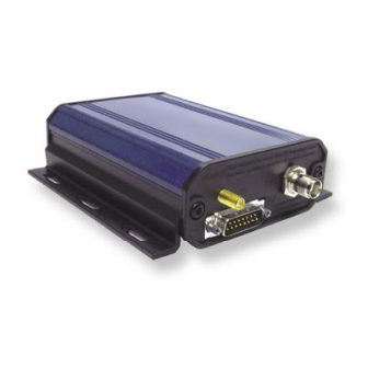
Summary of Contents for Navman Halo Qube 2
-
Page 1: Installation Manual
Europe / New Zealand Edition Halo QUBE 2 V1.0 Installation Manual... -
Page 2: Important Notice
Product may not perform at its designed potential or specifications. If in doubt, consult your Navman dealer. Ensure that any mounting holes that are cut in the vehicle are in a safe position and will not weaken the vehicle’s structure or compromise the safety of the vehicle or its occupants. -
Page 3: Table Of Contents
Halo QUBE 2 Installation Manual V1.0 Contents Introduction ................4 What comes with the Halo QUBE 2 ........4 Quick Install - 3-Wire Basic Tracking ........5 Installation ................6 Wiring ................... 8 Connecting an External ConEX .......... 11 Testing ................12 Fault Finding ............... -
Page 4: Introduction
Installation Guide V1.0 Introduction The Navman Halo Qube 2 is an Automatic Vehicle Location unit (AVL) that is installed into fl eet vehicles. It communicates with a server, allowing vehicle information to be stored and monitored. It is a combined GPS (Global Positioning System) and communications product that contains: •... -
Page 5: Quick Install - 3-Wire Basic Tracking
Halo QUBE 2 Installation Manual V1.0 Quick Install - 3-Wire Basic Tracking Power Connection Wire Colour Function Description +12/24 V Main Power Connection - Connect to fused supply Positive input from vehicle when the key is in the IGNITION position (not the accessory position). This signal must... -
Page 6: Installation
Halo QUBE 2 Installation Guide V1.0 Installation Location / Mounting Install the Qube 2: • Under the driver or passenger’s seat • In or under the dash • In the boot / trunk area The chosen location should: • Allow for later connection of the MDT or PDT. -
Page 7: Gps Antenna
Halo QUBE 2 Installation Manual V1.0 Antenna Position the antennas so that: • The GPS antenna has a clear view of as much of the sky as possible. • They are mounted as far away as practical from any other antenna, to minimize the risk of interference. -
Page 8: Wiring
Halo QUBE 2 Installation Guide V1.0 Wiring Cable A Has a long cable with a RJ45 Plug, a short cable with a DB9 plug, and a single cable with bare ends for all other connections. Cable B Has an RJ45 socket very close to the main plug (DB15), and a single long cable with bare ends for all other connections. -
Page 9: Digital Inputs
Halo QUBE 2 Installation Manual V1.0 Connecting the Auxiliary Devices The Qube 2 is equipped with additional IO that can be connected to auxiliary devices in the vehicle. These Allow the Qube to generate events based on inputs from these devices. -
Page 10: Digital Outputs
Halo QUBE 2 Installation Guide V1.0 Analogue Inputs These connect to devices that have a variable voltage output. As the input voltage range (0 to 5 V DC) may not match the sensors range, the input may have to be scaled. In order to scale the voltages correctly, you should calculate the maximum sensor voltage to scale to 5 V DC at the ConEX input. -
Page 11: Connecting An External Conex
Halo QUBE 2 Installation Manual V1.0 Connecting an External ConEX Note: Please check with your distributor, to see if this feature is available yet. An external ConEX would be connected if: The user requires additional IO lines, additional serial capture port, or has custom ConEX code that needs to be used with their system. -
Page 12: Testing
Halo QUBE 2 Installation Guide V1.0 Testing Check Correct Ignition connection Use a multi-meter to measure the voltage at the ignition line connected to the Qube 2. 1. Turn the key to the accessories position. Check that there is no voltage on the ignition line. -
Page 13: Specifications
Halo QUBE 2 Installation Manual V1.0 Specifications Dimensions: Height = 42mm Physical Serial Interface • Weight: 370g • RS232 x2 • Case Material: Aluminium Extrusion. Digital Inputs • End Caps: Bayblend FR110. Fire • Input Voltage LOW: < 1.0 V retardant ABS/Polycarb blend. -
Page 14: Conditions Of Sale & Warranty
Warranty Period - 1 year from the date of purchase. Extent of warranty - Subject to the following conditions Navman will rectify any defect occurring in the product of which notice in writing is received by Navman or its approved distributor within the Warranty Period. -
Page 15: Contacts
Halo QUBE 2 Installation Manual V1.0 Contacts Navman Wireless UK Navman NZ Limited 13-17 Kawana Street, Northcote Innovation Centre 2 PO Box 68 155, Newton Keele University Science Park Auckland Keele, Staffordshire, ST5 5NH UNITED KINGDOM NEW ZEALAND Tel: +64 (0)9 481 0500... -
Page 16: Notes
Halo QUBE 2 Installation Guide V1.0 Notes MN000032A...


Need help?
Do you have a question about the Halo Qube 2 and is the answer not in the manual?
Questions and answers