
Related Manuals for Navman Qube 2.5


Summary of Contents for Navman Qube 2.5
-
Page 1: Installation Manual
G P S T R A C K I N G A N D F L E E T M A N AG E M E N T S O L U T I O N S Qube 2.5 Installation Manual.indd 1 Qube 2.5 Installation Manual.indd 1... -
Page 2: Table Of Contents
Installing the Qube 2.5 in a Vehicle ....... . 8... -
Page 3: Introduction
1.1 Important Notice It is the Owner’s sole responsibility to install and use the Qube 2.5 (the Product) in a manner that will not cause accidents, personal injury or property damage. For the purpose of this notice, “Owner”, “you” and “your” means the party (including any person authorised by that party to use and/or install the Product) that has either: (a) purchased the Product;... -
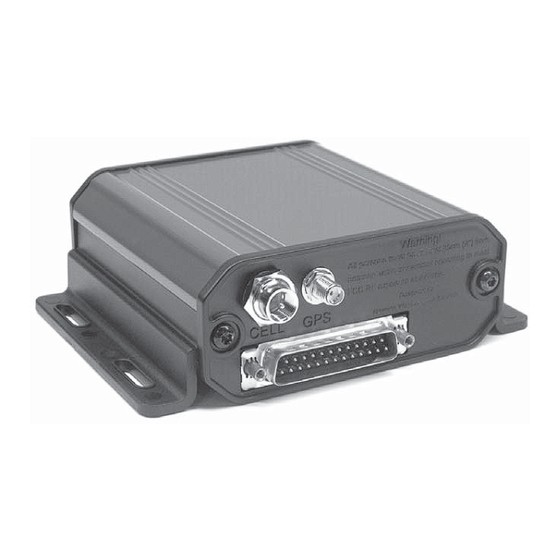
Page 4: Qube 2.5 Hardware
Qube 2.5 | Installation Manual 2 Qube 2.5 Hardware 2.1 Box Contents Qube 2.5 unit with mounting rails Vehicle connection cable Qube 2.5 Installation Manual G P S T R A C K I N G A N D F L E E T M A N AG E M E N T S O L U T I O N S Qube Installation Manual.indd 1... -
Page 5: Quick Install - 4 Wire Basic Tracking
3.3 Status LED Indicators Display State Normal Operation Description Power ON, Unit awake Slow Blink Sleep mode No Power – the Qube 2.5 should always be powered GPS fi x No GPS fi x Cell Data connection to cellular network No data connection Qube 2.5 Installation Manual.indd 7... -
Page 6: Installing The Qube 2.5 In A Vehicle
Mount the unit using the supplied self-tapping screws and washers, placed through the slots in the side rails. The side mounting rails are supplied fi tted to the Qube 2.5 ready for installation. If a different mounting format is required, the mounting rails may be turned over or removed completely. -
Page 7: Antenna
They are mounted as far away as practical from any other antenna, to minimize the risk of interference • The cables can be easily routed to the Qube 2.5 IMPORTANT NOTICE The cellular antenna must be placed at least 20 cm (8”) away from any person to meet FCC RF exposure requirements. -
Page 8: Wiring
Insulate bare wires 5.2 Connecting the Auxiliary Devices The Qube 2.5 is equipped with additional IO that can be connected to auxiliary devices in the vehicle. These allow the Qube to generate events based on inputs from these devices. •... -
Page 9: Digital Inputs
Qube 2.5 | Installation Manual 18-Wire cable Function Description Yellow Multi IO-1 Digital input, analogue input, digital output Green Multi IO-2 Digital input, analogue input, digital output Blue Multi IO-3 Digital input, analogue input, digital output Gray Multi IO-4 Digital input, analogue input, digital output Black A –... -
Page 10: Analogue Inputs
Connect the Orange wire directly to the positive of the backup battery, and ground the negative side of the battery at the same point as the Qube 2.5’s Black wire is grounded. If the Qube 2.5 is powered off 24V DC, then the Backup battery must also be 24V DC. If powered from 12V DC the Battery must be 12V DC. -
Page 11: Testing
Watching the meter, start the vehicle and ensure that the voltage does remain ON during starting If any of these tests fail, the Qube 2.5 is not connected to the correct signal. Please fi nd the correct wire. 6.2 Check Data and GPS... -
Page 12: Fault Finding
Qube 2.5 | Installation Manual 7 Fault Finding Fault Resolution Power LED fails to light Check that there is permanent power on the wire to which the Qube 2.5 was connected GPS LED fails to light Ensure that the antenna is up the correct way, and has a clear view... -
Page 13: Dimensions
Qube 2.5 | Installation Manual 8 Dimensions Qube 2.5 Installation Manual.indd 15 Qube 2.5 Installation Manual.indd 15 7/8/08 12:09:01 PM 7/8/08 12:09:01 PM... -
Page 14: Specifi Cations
Qube 2.5 | Installation Manual 9 Specifi cations Physical Digital Inputs • Weight: 322g • Input Voltage LOW: <1.0V • Case Material: Aluminium Extrusion • Input Voltage HIGH: >4.0V • End Caps and Side Rails: Bayblend • Absolute Maximum Voltage: 30V FR110. - Page 16 Qube 2.5 | Installation Manual Notes Qube 2.5 Installation Manual.indd 18 Qube 2.5 Installation Manual.indd 18 7/8/08 12:09:03 PM 7/8/08 12:09:03 PM...
- Page 17 MN000740B-G Lat 42° 6’ 16.98” N Lon 87° 49’ 29.27” W Qube 2.5 Installation Manual.indd 20 Qube 2.5 Installation Manual.indd 20 7/8/08 12:09:03 PM 7/8/08 12:09:03 PM...
Need help?
Do you have a question about the Qube 2.5 and is the answer not in the manual?
Questions and answers