Table of Contents
Troubleshooting

Related Manuals for Navman Qube 300


Summary of Contents for Navman Qube 300
-
Page 1: Installation And Troubleshooting Guide
1 Installation and Troubleshooting Guide Navman Wireless Installation and Troubleshooting Guide October 22, 2014 Version Number and status: 1.0 Document Date: October 22, 2014 Security Classification: Internal Use Only Document Owner: Gene Guller... -
Page 2: Table Of Contents
1.13.1 Qube 300 is not powering up (All LEDs Off) 1.13.2 Qube 300 is not reporting in OnlineAVL2 (Cellular Connectivity Issues) 1.13.3 Qube 300 is reporting to AVL2 but shows invalid location (GPS Fix Issues) 1.13.4 Qube is reporting to AVL2 but displays “Power up + Ignition On” icons. - Page 3 1 Installation and Troubleshooting Guide 1.13.8 Hardware Swap Procedure: determining faulty piece of hardware 1.13.9 Power: M-Nav will not power, M-Nav loses power unexpectedly, M-Nav turns on and off while in use. 1.13.10 Messaging: M-Nav can’t send or receive messages 1.13.11 Driver ID: Driver Logon function not working 1.14 Dimensions and Specifications 1.15 Contacts...
- Page 4 1 Installation and Troubleshooting Guide Disclaimer It is the Owner’s sole responsibility to install and use the Qube 300 (the Product) in a manner that will not cause accidents, personal injury or property damage. For the purpose of this notice, “Owner”, “you” and “your” means the party (including any person authorized by that party to use and/or install the Product) that has either: (a) purchased the Product;...
-
Page 5: Introduction
1 Installation and Troubleshooting Guide 1.1 Introduction 1.1.1 Overview The Navman Wireless Qube 300 is an Automatic Vehicle Location unit (AVL) that is installed into fleet vehicles. It communicates with a server and allows vehicle information to be stored and monitored. -
Page 6: Recommended Installation Practices
1 Installation and Troubleshooting Guide 1.2 Recommended Installation Practices Review this installation manual to become familiar with all installation procedures and elec- trical wiring requirements prior to starting the installation. This installation guide has been pre- pared to provide you with details necessary to complete the Qube installation. Use of proper tools and testing equipment is required. -
Page 7: Recommended Tools And Supplies
1 Installation and Troubleshooting Guide 1.3 Recommended Tools and Supplies 1.3.1 Basic Tools Wire Strippers Connector Crimping Tool Panel Removal Tool Digital Multimeter (DMM) T-10S Security Torx Screwdriver 1.3.2 Basic Supplies Wire Ring Terminals Cable Zip-Ties Electrical Tape Spare Fuses (Mini 3A) Self-Tapping Screws... -
Page 8: Qube 300 Hardware
1.4.1 Qube 300 Box Contents NOTE: You can use a combi-antenna OR a separate GPS Antenna and a separate Cellular Antenna. Contact your Navman Wireless dealer for advice on the best choices for your type of install- ation and for ordering information, if necessary. -
Page 9: Qube Installation Supplies Kit (Us Only)
The 3-Wire Power cable, the GPS Antenna, and the Cellular Antenna are the minimal requirement for tracking only. 1.4.2 Qube Installation Supplies Kit (US only) To allow for quicker and easier installations, Navman Wireless designed an all-in-one antenna system that includes both GPS and cellular components built into same housing. -
Page 10: Gps/Cellular Combination Antenna
1 Installation and Troubleshooting Guide 1.4.3 GPS/Cellular Combination Antenna... -
Page 11: Qube 300 Hardware
Insert the two short secur- ity screws into the screw holes on the outer edges of the Qube 300 , and the long security screw into the center hole. Tighten all three security screws using a Torx T10 security screwdriver. - Page 12 1 Installation and Troubleshooting Guide...
-
Page 13: Qube 300 Power Harness
1 Installation and Troubleshooting Guide 1.4.6 Qube 300 Power Harness... -
Page 14: Mounting The Antenna
1 Installation and Troubleshooting Guide 1.5 Mounting the Antenna 1.5.1 Exposed Install Using the attached double-sided tape pad, mount the antenna in the upper or lower corner of the vehicle’s windshield. Tuck the wires behind the A-pillar panel and run under the dash to the Qube’s location. -
Page 15: Qube 300 Mounting
Attention: The Qube 300 contains an accelerometer that detects vehicle movements. This func- tionality may be used to track driver behavior on the road. It is critical that the Qube 300 is mounted securely and cannot move independently of the vehicle OR vibrate off its mounting loc- ation. - Page 16 1 Installation and Troubleshooting Guide 3-Wire Colour Function Description Vehicle Ground/chassis con- Black nection. Main power connection (main vehicle supply). This connection +12/24V DC must be fused (3 Amp Slow Blow). Positive input from vehicle when the key is in the IGNITION pos- ition (not the Accessory position).
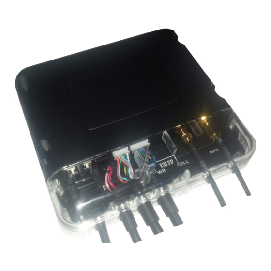
- Page 17 1 Installation and Troubleshooting Guide 4. Screw the GPS Antenna connector to the GPS connector at position 7. 5. Secure both antenna connectors using an open-ended 8mm spanner. Complete the installation by securing all wires with zip-ties, away from any moving parts or sharp metal edges.
-
Page 18: Identifying Correct Wires
2. Attach fuse holders to the Constant (Red) and the Ignition (Pink) wires of the Qube’s power harness. 3. Navman Wireless recommends locating and sourcing constant power and ignition con- nections at the ignition key wiring harness located behind ignition key cylinder. - Page 19 1 Installation and Troubleshooting Guide NOTES: After appropriate wires have been identified, it is strongly recommended that one of the battery post cables is disconnected prior to making wire connections. If the vehicle has a master battery disconnect switch, Qube’s power must be sourced at the battery or the hot side of the master battery disconnect switch.
-
Page 20: Poke & Wrap" Solder-Less Connections
1 Installation and Troubleshooting Guide 1.7.3 "Poke & Wrap" Solder-less Connections The recommended method of connecting wires is by soldering. As an alternative, when working inside the cab or any weatherproof environment, a “Poke & Wrap” method for solder-less con- nections will be acceptable. NOTE: During the “Poke &... - Page 21 1 Installation and Troubleshooting Guide NOTE: To ensure long lasting secure connections, do not use butt connectors, t-taps or fuse taps in your installation.
-
Page 22: Chassis Ground Connection
1 Installation and Troubleshooting Guide 1.8 Chassis Ground Connection Connect the Qube’s Ground wire (black) to vehicle’s chassis. For a solid connection, use a ring tongue terminal connector, star washer and a self-tap- ping screw. Do not ground under existing bolts that hold brackets or panels in place. -
Page 23: Mobile Data Terminal: M-Nav 800
Route the M-Nav800 Power/Data cable from the Qube to the top of dashboard, where M- Nav800 will be mounted. Use the supplied suction cup mount or the optional dash mount bracket to secure the device in place. Plug into the Data Port (RJ45) on the Qube 300. - Page 24 1 Installation and Troubleshooting Guide...
-
Page 25: Conex Sensor Monitoring/Auxiliary Devices
The Qube 300 has 3 serial ports. Use these to connect to other Navman Wireless devices, such as an M-Nav or MDT, or to third-party equipment for serial capture. The Qube 300 also has sev- eral digital and analogue I/O lines which can be connected to external sensors or equipment, using optional I/O cables as follows. -
Page 26: Digital Outputs
1 Installation and Troubleshooting Guide Active Low Input Configuration When configured as an Active Low Input, the input state is considered ON when it becomes low. The voltage thresholds that trigger the change in input state are as follows: 1.10.2 Digital Outputs DO-1 & DO-2 The Digital Outputs will pull to Ground and sink a maximum current of 250 mA when activated. -
Page 27: Qube Power Up Procedure
5. Wait for all LED lights on the Qube to stay on (not flashing). NOTE: If any LED’s are not solid On within 10 minutes, perform a Cold Reset. 6. Connect optional cables: ConEx, M-Nav, MDT, etc. 7. Log in to Navman Wireless Install Technician Service Portal to perform Live Test (US only). -
Page 28: Tamper-Evident Seal
1 Installation and Troubleshooting Guide 1.12 Tamper-Evident Seal Apply Tamper-Evident Seal paste (Torque-Seal or inspector’s lacquer) to all “Poke and Wrap” connections, fuse holders and the ground screw. Once applied it sticks to the surface and dries hard over 24 hours. Once hard it will crack on removal making the tampering obvious. Attach the clear tamper-proof Security Cover with supplied T-10S security screws. -
Page 29: Troubleshooting
Qube’s wiring, including the main harness, fuses and fuse holders. If the spare Qube is not available, remove the original Qube from vehicle for replacement. 7. When all troubleshooting fails or replacement hardware is required, contact Navman Wireless Support from Contact list. Please, have Qube’s serial number and brief descrip-... -
Page 30: Qube 300 Is Not Reporting In Onlineavl2 (Cellular Connectivity Issues)
(CDMA variant does not use SIM). SIM card slot is spring-loaded, do not force SIM into/out of slot. If available, insert a SIM card from another Qube 300/HSPA followed by a Cold Reset. Check OnlineAVL2 if the Qube resumed normal operation. -
Page 31: Qube 300 Is Reporting To Avl2 But Shows Invalid Location (Gps Fix Issues)
1 Installation and Troubleshooting Guide 1.13.3 Qube 300 is reporting to AVL2 but shows invalid location (GPS Fix Issues) Attention: Qube may not be reporting correct GPS location or repeating last known location because the Qube’s antenna does not have clear view of sky, obstructed or defective. -
Page 32: Qube Is Reporting To Avl2 But Displays "Power Up + Ignition On" Icons
1 Installation and Troubleshooting Guide 1.13.4 Qube is reporting to AVL2 but displays “Power up + Ignition On” icons. This condition is most likely caused by improper connections of the Qube’s power wires to vehicle circuits. The installer may have connected the constant +12V wire or the ground wire from the Qube’s power harness to a switched source in vehicle. -
Page 33: Power Cycle/Cold Reset Procedure For M-Nav800
1.13.8 Hardware Swap Procedure: determining faulty piece of hardware 1. Verify that the Qube is functional and reporting to Online AVL2. 2. Call Navman Support to have the Qube’s serial port set to communicate with the M-Nav. If problem persists, proceed to next step. - Page 34 Awake, modem ON: 70 mA (35 mA) Awake, average transmit event once Temperature Monitoring Maximum of six Navman Wireless every one minute: 120 mA (60 mA) Peak transmit current: 250 mA (130 mA) digital temperature probes Battery charging: additional 150 mA (80...
- Page 35 1 Installation and Troubleshooting Guide Digital Inputs Serial Interface Input Voltage LOW: <1.0 V (Active High RS232 x 3 mode) Input Voltage HIGH: >5.0 V (Active High Environmental mode) Storage Temperature: -40 to +85°C (-40 Input Voltage LOW: <0.2 V (Active Low to +185°F) mode) Operational Temperature: -20 to +70°C...
- Page 36 1 Installation and Troubleshooting Guide RJ45 Connector Function Description Ground +12/24 V DC Power Output, as per vehicle supply RTS-1 Serial Port 1 (Input) Ready To Send Flow Control RXD-1 Serial Port 1 (Input) Data TXD-1 Serial Port 1 (Output) Data CTS-1 Serial Port 1 (Output) Clear To Send Flow Control 8-Way Expansion Pin Connector...
- Page 37 Email: support_tw@navmanwireless.com Fax: + 86 0 21 3218 1052 Website: www.navmanwireless.com.au Email: support_cn@navmanwireless.com Website: www.navmanwireless.cn Navman Wireless de México Calzada San Pedro #100, Col. del Valle, Pedro Garza García, Nuevo Léon. CP 66220, MéxicoTeléfono: +52(81) 8248.4600 ext 1001Email: soporte@navmanwireless.com Website: www.navmanwireless.com.mx...
Need help?
Do you have a question about the Qube 300 and is the answer not in the manual?
Questions and answers
I removed the cube & some of the related wiring..Walked away from the truck. 2016 F150 ...It sat for 2 days..& when I went to start it I have pretty much no power coming into the instrument cluster & cab fuse panel.. What did I do plz