Table of Contents
Advertisement
Quick Links
Advertisement
Table of Contents

Related Manuals for DeVilbiss GFG HD


Summary of Contents for DeVilbiss GFG HD
- Page 1 SB-E-2-811 ISS.04 Technical Bulletin GFG HD – Gravity Spray Gun...
-
Page 2: Table Of Contents
Table of Contents Topic Page EC Declaration of Conformity Part Numbers Operational Description Kit contents Construction Features Materials of Construction Specifications & Technical Data Safety Precautions Parts List Exploded parts View Installation, Operation, Preventive Maintenance & Cleaning Parts Replacement/Maintenance A. Servicing Air Valve B. -
Page 3: Ec Declaration Of Conformity
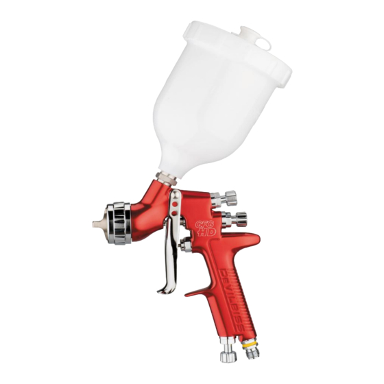
Finishing Brands UK Limited reserves the right to modify equipment specification without prior notice. Part Numbers The GFG HD Sprayguns are available with 2 alternative Aircaps and 3 Nozzles.C1 for base and clearcoat application. C2 is used for higher viscosity materials. The ordering code for the spray guns is;... -
Page 4: Kit Contents
Interchangeable Colour ID System (4 coloured Fluid Needle (grooved stem for easy removal) rings supplied) Anodised, forged aluminium gun body Fluid Inlet (3/8 BSP thread – accepts DeVilbiss and (ergonomic, good looking & durable, easy to most other cup systems) clean) Air Inlet (universal thread, accepts G 1/4 &... -
Page 5: Safety Precautions
SAFETY WARNINGS Fire and explosion Solvents and coating materials can be highly flammable or combustible when sprayed. ALWAYS refer to the coating material supplier’s instructions and COSHH sheets before using this equipment. Users must comply with all local and national codes of practice and insurance company requirements governing ventilation, fire precautions, operation and house-keeping of working areas. -
Page 6: Parts List
PARTS LIST REF. REF. DESCRIPTION PART NO. DESCRIPTION PART NO. Air Cap Retaining Ring Air Valve Cage Slip Ring Air Valve Poppet Air Cap Air Valve Spring Air Cap Retaining Clip JGA-156-K5 Air Valve Spring Pad SN-34-K5 Retaining Ring Seal Air Valve Seal C1 Aircap &... -
Page 7: Exploded Parts View
© 2012 Finishing Brands UK Ltd. -
Page 8: Installation, Operation, Preventive Maintenance & Cleaning
INSTALLATION instrument is used, extreme care must be used to prevent scratching or burring of the holes which will For maximum transfer efficiency, do not use more cause a distorted spray pattern. pressure than is necessary to atomise the material being applied. -
Page 9: Parts Replacement/Maintenance
Parts Replacement/Maintenance AIR VALVE INSTRUCTIONS Servicing Air Valve Reasons to service air valve: A) Air valve not functioning correctly (may need cleaning). B) Routine maintenance. C) Air leaks (advise replacement, see p10) 1. Remove trigger using the tool supplied (SPN-8) or TORX T20 key. -
Page 10: Replacing Air Valve
Replacing Air Valve Reasons to replace air valve: A) Air leak through the gun. B) Air valve not operating correctly. 1. Remove trigger using SPN-8 or TORX (T20) key provided in the kit. (See figs 13 & 14) 2. Unscrew air valve using SN-28 (14 mm) Spanner. (See fig 15) 3. -
Page 11: Needle Packing, Fluid Insert, Spreader Valve Assembly
Parts Replacement/Maintenance NEEDLE PACKING REPLACEMENT INSTRUCTIONS 13. Remove trigger using SPN-8 or TORX (T20) driver. (See figs 25 & 26) 14. Remove fluid adjusting knob and needle spring with spring pad from gun. (See figs 27 & 28) 15. Remove fluid needle from gun body. (See fig 29) 16. -
Page 12: Spray Head Seal
Parts Replacement/ Maintenance SPRAY HEAD SEAL REPLACEMENT 1. Remove air cap and retaining ring. (See fig 37) 2. Remove fluid adjusting knob, spring, and spring pad. (See figs 38 & 39) 3. Remove fluid needle from gun body. (See fig 40) 4. - Page 13 Parts Replacement/Maintenance Chart 1 – Air Caps PART No. FOR AIR TECHNOLOGY MARKING ON AIR RECOMMENDED AIR FLOW INLET PRESSURE (L/min) (bar) PROC-120-C1-K CONVENTIONAL 2.5 – 3.0 250 - 300 PROC-120-C2-K CONVENTIONAL 2.5 - 4.0 255 - 400 NOTE: When removing air cap from retaining ring, don’t remove the Slip Ring (2) or Retaining Ring Seal (5) from the Retaining Ring.
-
Page 14: Troubleshooting Possible Problems In Operation
Troubleshooting Possible Problems in Operation CONDITION CAUSE CORRECTION Heavy top or Horn holes plugged. Clean. Ream with non-metallic point. bottom pattern Clean. Obstruction on top or bottom of fluid nozzle. Clean. Cap and/or nozzle seat dirty. Clean. Ream with non-metallic point. Left or right side horn holes plugged. - Page 15 Troubleshooting Possible Problems in Operation (cont) Inadequate material flow Wind fluid adjusting knob out or change to larger fluid nozzle size Starved spray pattern Blocked vent in Cup lid Clean lid and unblock vent Low atomisation air pressure Increase air pressure and rebalance gun.
-
Page 16: Accessories
ACCESSORIES DGi PRO Digital Pressure DGIPRO-502-BAR Gun Stand GFV-50-F Gauge 600 cc Mixing Spanner Cups pack of MC-1-K50 10m x 8mm bore rubber air H-6065-B (BSP) SN-406 Torx driver hose with ¼ H-6065-N (NPS) fittings Pack of four Cleaning Brush MPV-463 QD fittings Cleaning Brush...
Need help?
Do you have a question about the GFG HD and is the answer not in the manual?
Questions and answers