Sign In
Upload
Manuals
Brands
Broadcom Manuals
Computer Hardware
Brocade X7-8
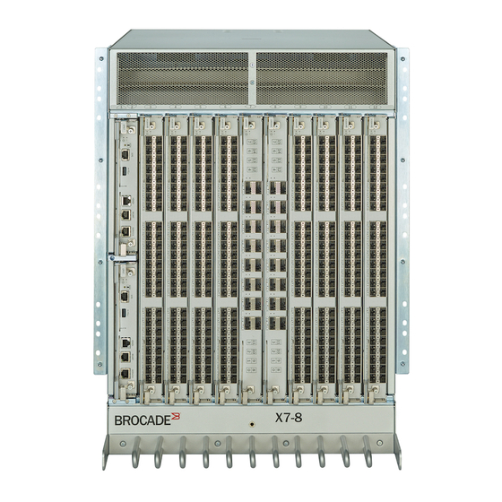
User Manuals: Broadcom Brocade X7-8 Network Switch
Manuals and User Guides for Broadcom Brocade X7-8 Network Switch. We have
1
Broadcom Brocade X7-8 Network Switch manual available for free PDF download: Installation Manual
Broadcom Brocade X7-8 Installation Manual (212 pages)
Director Hardware
Brand:
Broadcom
| Category:
Computer Hardware
| Size: 6 MB
Table of Contents
Table of Contents
2
Copyright Notice
8
Introduction
9
About this Document
9
Supported Hardware
9
Notes, Cautions, and Danger Notices
11
Contacting Technical Support for Your Brocade ® Product
11
Document Feedback
12
Device Overview
13
Product Features
13
Hardware Components
14
Port-Side View of the Device
15
Port-Side Slot Numbering
17
Nonport-Side View of the Device
17
Preparing for Installation
19
Safety Precautions
19
Facility Requirements
21
Time and Items Required
21
Shipped Items
23
Quick Installation Checklists
23
Mounting the Device
26
Mounting Options
26
Mounting Precautions
26
Unpacking and Transporting the Device
27
Installing the 14U Rack Mount Kit for Four-Post Racks (XBR-DCX-0120 and XBR-DCX-0152)
27
Time and Items Required
28
Parts List
28
Assembling the Rack Hardware
29
Installing the Device in the Rack
32
Installing the 14U Chassis MID-Mount Rack Kit for Two-Post Racks (XBR-DCX-0121)
35
Time and Items Required
35
Parts List
35
Assembling the Rack Hardware
37
Installing the Device in the Rack
38
Initial Setup and Verification
42
Configuration and Verification Task Guide
42
Items Required
43
Providing Power to the Device
43
Connecting the Power Cord to AC Power Supplies
44
Connecting to HVAC/HVDC Power Supplies
44
Using HVAC/HVDC Power Cords
47
Establishing a Serial Connection to the Device
48
Configuring the IP Addresses
50
Establishing an Ethernet Connection to the Device
51
Setting the Domain ID
52
Setting the Date and Time
52
Setting the Time Zone
53
Synchronizing the Local Time with an External Source
54
Customizing the Chassis and Switch Name
54
Verifying Installed Licenses and the License Key
55
Verifying Correct Operation
56
Backing up the Configuration
56
Powering down the Chassis
57
Installing Transceivers and Cables
60
Supported Transceivers and Cables
60
Port and Extension Blade Transceivers
62
Core Routing Blades
63
Time and Items Required
65
Precautions Specific to Transceivers and Cables
65
Cleaning the Fiber-Optic Connectors
66
Cable Management
66
Installing an SFP+ Transceiver
66
Replacing an SFP+ Transceiver
68
Installing a QSFP Transceiver
69
Replacing a QSFP Transceiver
70
Verifying the Operation of New Transceivers
71
Monitoring the Device
72
Introduction
72
Interpreting FC32-X7-48 Port Blade Leds
72
Interpreting FC64-48 Port Blade Leds
74
Interpreting FC32-64 Port Blade Leds
76
Interpreting Extension Blade Leds
79
Interpreting Control Processor Blade Leds
81
Interpreting Core Routing Blade Leds
83
Interpreting WWN Card Leds
85
Interpreting Power Supply Leds
86
Interpreting Fan Assembly Leds
89
Interpreting POST and Boot Results
90
Post
90
Boot
91
Optical Transceiver Requirements
91
Using Monitoring Commands
91
Errdump and Errshow
92
Fanshow
92
Hashow
92
Historyshow
93
Psshow
95
Sensorshow
95
Sfpshow
96
Slotshow
102
Supportsave
102
Tempshow
105
Running Diagnostic Tests
106
Port and Extension Blades
108
FC32-X7-48 Port Blade Overview
108
FC32-X7-48 Port Blade Numbering and Trunking
108
FC64-48 Port Blade Overview
110
FC64-48 Port Blade Numbering and Trunking
111
FC32-64 Port Blade Overview
113
FC32-64 Port Blade Numbering and Trunking
114
Extension Blade Overview
116
Extension Features
117
SX6 Blade Port Numbering and Trunking
118
Blade-Specific Precautions
119
Faulty Blade Indicators
119
Time and Items Required for Removal and Installation
120
Removing a Blade
120
Installing a Blade
122
Verifying Blade Operation
123
Core Routing Blades
124
Core Routing Blade Overview
124
CR64-8 Port Numbering
124
ICL Trunking Groups
126
ICL Cabling Configurations
127
Blade-Specific Precautions
129
Faulty Core Routing Blade Indicators
130
Time and Items Required
130
Replacing a Core Routing Blade
131
Preparing for Replacement
131
Removing a Core Routing Blade
132
Installing a Core Routing Blade
133
Verifying Blade Operation
134
Control Processor Blades
136
Control Processor Blade Overview
136
CPX7 Port Identification
136
Blade-Specific Precautions
137
Blade Fault Indicators
138
Blade Replacement Task Guide
138
Time and Items Required for Replacement
139
Preparing for Replacement
139
Replacing a CP Blade
140
Hot-Swap Procedure
141
Removing a Blade
141
Installing a Blade
142
Verifying and Synchronizing Firmware on Blades
143
Cold-Swap Procedure
147
Removing a Blade
147
Installing a Blade
148
Completing the Replacement
149
Verifying Blade Operation
150
WWN Cards
151
WWN Card Overview
151
WWN Card Location and Numbering
151
Precautions Specific to WWN Cards
152
WWN Card Fault Indicators
152
WWN Card Replacement Task Guide
154
Time and Items Required for Replacement
154
Using the Wwnrecover Utility
154
Preparing for WWN Card Replacement
156
Hot-Swap Replacement
157
Cold-Swap Replacement
158
Removing the WWN Card and Bezel
160
Configuring the Airflow Direction on WWN Cards
161
Verifying WWN Card Operation
161
Power Supply Assemblies
162
AC Power Supply Overview
162
HVAC/HVDC Power Supply Overview
163
Power Supply Assembly Numbering
164
Fan and Power Supply Airflow
165
Precautions Specific to Power Supply Assembly
166
Power Supply Assembly Fault Indicators
166
Power Supply Assembly Task Guide
166
Time and Items Required
167
Removing a Power Supply
168
Installing a Power Supply
170
Verifying Power Supply Operation
170
Fan Assemblies
171
Fan Assembly Overview
171
Fan and Power Supply Airflow
172
Fan Assembly Numbering
173
Precautions Specific to Fan Assemblies
174
Fan Assembly Fault Indicators
175
Fan Assembly Task Guide
175
Time and Items Required
176
Removing a Fan Assembly
176
Installing a Fan Assembly
177
Verifying Fan Operation
178
Blade Filler Panels
179
Blade Filler Panel Removal and Replacement
179
Removing a Filler Panel
179
Installing a Filler Panel
180
Cable Management Comb
182
Cable Management Comb Overview
182
Time and Items Required for Removal and Installation
182
Removing the Cable Management Comb
183
Installing the Cable Management Comb
183
Chassis Door
184
Chassis Door Overview
184
Time and Items Required
184
Removing a Chassis Door
184
Installing a Chassis Door
185
Replacing the Chassis
187
Chassis Replacement Overview
187
Precautions Specific to Chassis Replacement
187
Chassis Replacement Task Guide
187
Chassis Fault Indicators
188
Time and Items Required
188
Preparing for Replacement
189
Recording Critical Device and SAN Information
189
Disconnecting from the Network and Fabric
193
Removing Components from the Chassis
193
Installing the Replacement Chassis
194
Installing Components into the Chassis
194
Synchronizing Airflow Direction on WWN Cards
195
Downloading the Configuration
196
Reconnecting the System to the Network and Fabric
196
Verifying Correct Operation of the System
197
Verifying Correct Configuration of the Fabric
198
Regulatory Statements
200
BSMI Statement (Taiwan)
200
Canadian Requirements
200
CE Statement
200
China ROHS
200
FCC Warning (U.S. Only)
200
KCC Statement (Republic of Korea)
201
VCCI Statement
201
Cautions and Danger Notices
202
Cautions
202
Danger Notices
207
Revision History
211
Advertisement
Advertisement
Related Products
Broadcom Brocade X6-8 Director
Broadcom Brocade X6-4
Broadcom Brocade X7-4 Director
Broadcom Brocade DCX 8510-4 Backbone
Broadcom Brocade G720
Broadcom Brocade G630-1
Broadcom Brocade G630-2
Broadcom Brocade G630
Broadcom Brocade G730
Broadcom Brocade Fabric OS 6505
Broadcom Categories
PCI Card
Motherboard
Adapter
Controller
Computer Hardware
More Broadcom Manuals
Login
Sign In
OR
Sign in with Facebook
Sign in with Google
Upload manual
Upload from disk
Upload from URL