Assa Abloy MSL mFlipLock access Assembly And Operating Instructions Manual
Hide thumbs
Also See for MSL mFlipLock access:
- Assembly and operating instructions manual (136 pages)
Table of Contents
Advertisement
Available languages
Available languages
Quick Links
mFlipLock
mFlipLock access / FlipLock e-access
25574PE-SV 25574PE-SV-ZF / 26576PB-SV 26576PB-SV-ZF
Montage- und Bedienungsanleitung / Assembly and operating instructions /
Instruction de montage et d'utilisation / Istruzioni per l'uso e il montaggio
CHMSL1444002
www.assaabloy.ch
DE Seite
EN Page
FR
Page
IT
Pagina 110
ASSA ABLOY, the global leader
in door opening solutions
2
38
74
Advertisement
Chapters
Table of Contents

Related Manuals for Assa Abloy MSL mFlipLock access


Summary of Contents for Assa Abloy MSL mFlipLock access
- Page 1 / FlipLock e-access 25574PE-SV 25574PE-SV-ZF / 26576PB-SV 26576PB-SV-ZF Montage- und Bedienungsanleitung / Assembly and operating instructions / Instruction de montage et d’utilisation / Istruzioni per l’uso e il montaggio ASSA ABLOY, the global leader CHMSL1444002 in door opening solutions...
- Page 2 Lesen Sie diese Anleitung vor der Benutzung sorgfältig durch und bewahren Sie sie auf. Die Anlei- tung beinhaltet wichtige Informationen zum Produkt, insbesondere zum bestimmungsgemäßen Gebrauch, zur Sicherheit, Montage, Benutzung, Wartung und Entsorgung. Geben Sie die Anleitung nach der Montage an den Benutzer und im Falle einer Weiterveräußerung mit dem Produkt weiter.
-
Page 3: Table Of Contents
Inhaltsverzeichnis Produktinformation....4 Montage ......18 Produktbeschreibung . -
Page 4: Produktinformation
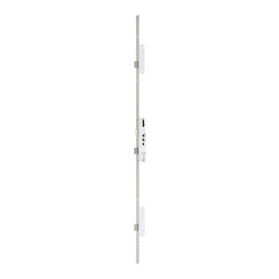
Produktinformation Produktbeschreibung mFlipLock access und mFlipLock e-access Das mFlipLock access und das mFlipLock e-access (Abb. 1) sind Panik-Sicherheits-Mehrpunktverriegelungen mit motorisierter Entriegelung, integrierter Statusrückmeldung, drei Riegeln und drei blockierenden Kippfallen (englisch: fliplatch) mit Geräuschdämmung. Durch die Kippfallen lässt sich die Tür auch unter hoher Vorlast öffnen. -
Page 5: Kennzeichnung Der Produktvarianten
Abb. 1 : Panik-Sicherheits- Beispiel einer Beispiel einer Mehrpunktverriegelung Produktvariante Produktvariante mFlipLock access/e-access für eine für eine einflügelige Tür zweiflügelige Tür Auswertesteuerung Kennzeichnung der Produktvarianten Tab. 1 : Kennung Bedeutung Produktvarianten PE / access mit Panikfunktion E („mFlipLock access mit Panikfunktion E“, Seite 15) PB / e-access mit Panikfunktion B (Umschaltfunktion) („mFlipLock e-access mit Panikfunktion B“, Seite 15) selbstverriegelnd... -
Page 6: Begriffserklärung
Begriffserklärung Nr. Benennung Begriffserklärung – Ruhestrom Das Schloss ist im stromlosen Zustand entriegelt. – Arbeitsstrom Das Schloss ist im stromlosen Zustand verriegelt. – Fluchttürfunktion / Eine Tür mit Fluchttürfunktion kann in Fluchtrichtung (in der Regel von innen) jederzeit über den Türdrü- Panikfunktion cker geöffnet werden, auch die verriegelte Tür. - Page 7 Abb. 2 : Schematische Darstellung des Schlosses mFlipLock access/e-access Abb. 3 : Funktionsluft Produktinformation...
-
Page 8: Hinweise
Hinweise Zu dieser Anleitung Diese Installations- und Montageanleitung wurde für Handwerksfachkräfte und eingewiesenes Personal geschrieben. Lesen Sie diese Anleitung, um das Gerät sicher zu installieren, zu betreiben und die zulässi- gen Einsatzmöglichkeiten, die es bietet, auszunutzen. Die Anleitung gibt Ihnen auch Hinweise über die Funktion wichtiger Bauteile. Bedeutung der Symbole Gefahr! Sicherheitshinweis: Nichtbeachtung führt zu Tod oder schwerer Verletzung. -
Page 9: Sicherheitshinweise
Sicherheitshinweise Warnung! Lebensgefahr, Verletzungsgefahr durch verminderte Feuerschutzfunktion: Feuerschutztüren (auch Rauchschutztüren) verhindern den Durchtritt von Feuer (Rauch). Diese Türen werden als Ganzes geprüft: · Halten Sie bauaufsichtliche Vorschriften ein. · Prüfen Sie, dass die Zertifizierung der Schutztür zum Schloss passt. · Halten Sie die Vorgaben des Türherstellers ein. ·... - Page 10 Warnung! Ungeeignete Verschlüsse vermindern den Personenschutz und Feuerschutz: Das Schloss ist für Feuer- schutz- oder Rauchschutztüren geeignet („Klassifizierungsschlüssel“, Seite 16). · Prüfen Sie, ob die Zertifizierung der Tür zum Schloss passt. · Achten Sie darauf, dass das Schloss in passender Größe und mit dem passenden Zubehör eingebaut wird.
- Page 11 Achtung! Sachschaden durch Arbeiten am Türblatt: Vor Arbeiten am Türblatt, zum Beispiel Bohren oder Fräsen, müssen Sie das Schloss ausbauen. Funktionseinschränkung bei falscher Funktionsluft: Stellen Sie die Funktionsluft („Begriffserklärung“, Seite 6) passend ein („Technische Daten“, Seite 30) Sachschaden durch ungeeignetes Schließblech: Das Schließblech müssen Sie so auswählen und montie- ren, dass es immer die Anlauf- und Gleitfläche für die Schlossfalle bietet.
-
Page 12: Bestimmungsgemäßer Gebrauch
Bestimmungsgemäßer Gebrauch Die Panik-Sicherheits-Mehrpunktverriegelung mFlipLock access/e-access ist zum Einbau in ein- oder zweiflügelige Rohrrahmen-, Vollblatttüren oder für Türen mit Kunststoffprofilen geeignet. Es ist nicht zum Einbau in Pendeltüren geeignet. Das Schloss ist geeignet für Türverriegelungen in Sicherheitsbereichen und Rettungswegen entspre- chend folgender Normen: ·... -
Page 13: Funktionen Und Bedienung
Funktionen und Bedienung Selbstverriegelung Das Schloss ist mechanisch selbstverriegelnd und somit ist die Tür Abb. 5 : in geschlossenem Zustand immer verriegelt. Das Schloss entrie- Steuerfalle gelt über den Motorantrieb oder über eine mechanische Kippfalle Betätigung. Riegel Funktionsprinzip beim Verriegeln Beim Schließen der Tür werden die ausgefahrenen Kippfallen (Abb. -
Page 14: Kombination Mit Einem
Kombination mit einem Drehtürantrieb für barrierefreie Türen Wegen der integrierten motorisierten Entriegelung eignet sich das Schloss für die Kombination mit einem Drehtürantrieb, zum Beispiel für barrierefreie Türen, die automatisch entriegelt und geöffnet werden. Zutrittskontrollsystem Wegen der integrierten Statusrückmeldung im Schloss und der motorisierten Entriegelung kann das elektrische Entriegelung Schloss mit einem Zutrittskontrollsystem verbunden werden. -
Page 15: Produktvarianten
Produktvarianten mFlipLock access mit Panikfunktion E durchgehende Das mFlipLock access ist mit einer durchgehenden Drückernuss ausgestattet, so dass Innen- und Außendrü- Drückernuss cker immer angekoppelt sind. Typischerweise wird außen (entgegen der Fluchtrichtung) ein Beschlag mit Knauf und innen (in Fluchtrichtung) ein Fluchttürbeschlag montiert. Bei dieser Produktvariante zieht der Motor die Riegel ein und gibt die Kippfallen frei. -
Page 16: Klassifizierungsschlüssel
Klassifizierungsschlüssel EN 1125 Paniktürverschlüsse Der Klassifizierungsschlüssel beschreibt die Eigenschaften von Schlössern nach EN 1125. Tab. 4 erläutert den Klassifizierungsschlüssel. Tab. 4 : Klasse Bedeutung Klassifizierungsschlüssel nach EN 1125 Hohe Nutzungshäufigkeit, begleitet von nur wenig Anreiz zur Sorgfalt, wo die Möglichkeit eines Unfalls oder eines Missbrauchs gegeben ist 200.000 Prüfzyklen Türmasse bis 200 kg Geeignet für die Verwendung an Feuer- und Rauchschutztüren auf Grundlage einer Prüfung... -
Page 17: En 179 Notausgangsverschlüsse
EN 179 Notausgangsverschlüsse Der Klassifizierungsschlüssel beschreibt die Eigenschaften von Schlössern nach EN 179 Tab. 5 erläutert den Klassifizierungsschlüssel. Tab. 5 : Klasse Bedeutung Klassifizierungsschlüssel Hohe Nutzungshäufigkeit, begleitet von nur wenig Anreiz zur Sorgfalt, d. h., wo die Möglichkeit nach EN 179 eines Unfalls oder eines Missbrauchs gegeben ist 200.000 Prüfzyklen Türmasse bis 200 kg Geeignet für die Verwendung an Feuer- und Rauchschutztüren auf Grundlage einer Prüfung... -
Page 18: Montage
Montage Warnung! Prüfen auf Beschädigung: Beschädigungen der Kabel können zu Stromschlägen führen. Beschädigungen an den Metallteilen können zu Verletzungen führen. Ein beschädigtes Gerät ist ein Sicherheitsrisiko. · Ein beschädigtes Gerät dürfen Sie nicht in Betrieb nehmen. Auch beschädigte Kabel oder Steckverbin- dungen dürfen Sie nicht verwenden. - Page 19 Abb. 6: Sachschaden vermeiden max. 150 N Montage...
-
Page 20: Montieren
Montieren Warnung! Lebensgefahr durch Stromschlag: Eine unsachgemäße Verkabelung ist lebensgefährlich. · Lassen Sie die Stromversorgung ausschließlich von einer Elektrofachkraft anschließen. Vorsicht! Verletzungsgefahr durch scharfe Kanten und Späne: Beim Bohren und anderen zerspanenden Arbeiten besteht durch scharfe Kanten und Späne Verletzungsgefahr. ·... -
Page 21: Schloss Montieren
Schloss montieren Achtung! Tür vor unbeabsichtigtem Schließen schützen: Das Schloss verriegelt eine zugefallene Tür automatisch und kann danach nur über ein elektrisches Steuersignal oder über den Schließzylinder wieder entriegelt werden. · Bevor Sie die Tür mit eingebautem Schloss schließen, müssen Sie einen Schließzylinder montieren. Schloss verschrauben Verschrauben Sie das Schloss in der Schlosstasche. -
Page 22: Schloss Prüfen
Schloss prüfen Prüfen Sie alle Funktionen des Schlosses. Auf vollständige Funktionsfähigkeit Prüfen Sie, ob Fallen und Steuerfalle des Schlosses beim Schließen der Tür von derselben Aufschlag- prüfen kante zurück gedrückt werden („Profile mit thermischer Trennung“, Seite 22). Prüfen Sie, ob alle Riegel nach der Montage frei und ohne Querbelastung ein- und ausfahren können (Abb. -
Page 23: Schloss Manuell Prüfen
Schloss manuell prüfen Abb. 9: Manuelle Funktionsprüfung Montage... -
Page 24: Elektrischer Anschluss
Elektrischer Anschluss Auswertekontakte Das Schloss ist mit folgenden potentialfreien Auswertekontakten ausgestattet: Türstatus Steuerfallenkontakt Der Steuerfallenkontakt liefert Informationen über die Stellung der Steuerfalle. Steuerfalle eingedrückt Kontakt geschlossen Tür geschlossen Steuerfalle nicht eingedrückt Kontakt offen Tür offen Türdrückerstatus Türdrückerkontakt in Fluchtrichtung Der Türdrückerkontakt liefert Informationen über die Stellung des Türdrückers in Fluchtrichtung. Türdrücker betätigt Kontakt geschlossen Schloss mechanisch entriegeln... -
Page 25: Ruhestrom Oder Arbeitsstrom
Ruhestrom oder Arbeitsstrom Werkseitig ist das Schloss auf das Arbeitsstrom-Prinzip eingestellt: dass Schloss ist im stromlosen Zustand verriegelt. In Verbindung mit der Auswertesteuerung kann das Schloss auch im Ruhestromprinzip betrie- ben werden. Kabel verlegen und anschließen Das Anschlusskabel muss im Türblatt von der Schlossseite zur Bandseite geführt werden. Anschließend muss das Kabel vom Türblatt in den Türrahmen verlegt werden. - Page 26 Abb. 10 : Anschlussschema mFlipLock access Montage...
- Page 27 Nr. Beschreibung Nr. Beschreibung Türantrieb/Freigabe: Fabrikat Jumperstellung JP4: Werkseinstellung Pos. 1 Pos 2. 120 Ω an RS485 X18 Abschlusswiderstand bei Störungen Datenbus Störung: Steuerung: Öffner Kontakt Fingerleser: (RS 485 BUS) Türkontakt: Kontaktstellung abhängig vom Schloss (Steuerfalle) und MOD-BUS: WAGO Knoten (RS 485 BUS) Eingang X13 Zylinderkontakt: Kontakte schalten bei Betätigung des Zylinders Ausgang Speisung: sowie X15 ohne S1...
- Page 28 Abb. 11 : Anschlussschema mFlipLock e-access Montage...
- Page 29 Nr. Beschreibung Nr. Beschreibung Türantrieb/Freigabe: Fabrikat Jumper JP3: Werkseinstellung Pos. 1 Pos 2. 120Ω an RS485 X16 Abschlusswiderstand bei Störungen Datenbus Störung: Steuerung: Öffner Kontakt Jumperstellung JP4: Werkseinstellung Pos. 1 Pos 2. 120Ω an RS485 X18 Abschlusswiderstand bei Störungen Datenbus Türkontakt: Kontaktstellung abhängig vom Schloss (Steuerfalle) und Fingerleser: (RS 485 BUS) Eingang X13...
-
Page 30: Technische Daten
Technische Daten Tab. 6: Eigenschaft Ausprägung Technische Daten Dornmaß: Rohrrahmentür und Vollblatttür 30 mm bis 80 mm (in 5 mm Schritten) Entfernung bei Schweizer Rundzylinder 94 mm Entfernung bei Euro-Profilzylinder 92 mm Drückernuss 9 mm Funktionsluft 3 mm bis 6 mm Riegelausschluss 20 mm maximale Türmasse... - Page 31 Tab. 7 : Eigenschaft Ausprägung Elektrische Daten Betriebsnennspannung Gleichstrom (DC) 11 bis 27 V DC Nennstromaufnahme (maximal 1,5 s) 350 mA Stromverbrauch bei 24 V DC Stromaufnahme · Standby 24 mA · mit Auswertesteuerung 70 mA Datenkabel · Länge 10 oder 20 m ·...
-
Page 32: Zubehör
Zubehör Schließbleche Abb. 12: Schließbleche für Holz BV-24421.R3243.2 BV-24421.R3243.1 19,4 19,4 Zubehör... - Page 33 Abb. 13: Schließbleche für Metall BV-24421.R6333.2 BV-24421.R6333.1 19,4 19,4 Zubehör...
-
Page 34: Flexibler Kabelübergang
Flexibler Kabelübergang Der im Kapitel „Kabel verlegen und anschließen“, Seite 25 genannte flexible Kabelübergang zur Kabelführung vom Türblatt auf das Zargenprofil (oder die Wand) gehört nicht zum Lieferumfang des Schlosses. Der Kabelübergang kann separat bestellt werden: Panikdruckstange und Panikgriffstange Zubehör nach EN 1125 MSL Panikgriffstange 5971.294 für Europrofilzylinder Distanz 5971.392 für CH-Rundzylinder Distanz 94... -
Page 35: Wartung
Wartung www.assaabloy.ch Achtung! Unsachgemäße Schmierung beschädigt das Schloss: Das Schloss innen nicht einfetten. Keine Schmier- stoffe in das Schloss spritzen. Keine harzenden Fette verwenden. · Fetten Sie nur die äußeren Gleitflächen des Schlosses ein. Schmierstoff Hersteller Bemerkung Tab. 9: Empfohlene Schmierstoffe Klübersynth LI 44-22 Klüber Lubrication Falle und Riegel leicht benetzen... -
Page 36: Gewährleistung, Entsorgung
Gewährleistung, Entsorgung Gewährleistung Es gelten die gesetzlichen Gewährleistungsfristen und die Verkaufs- und Lieferbedingungen der ASSA ASSA ABLOY (Schweiz) AG (www.assaabloy.ch). Entsorgung Entsorgung nach EPD (Environmental Product Declaration). Führen Sie Verpackungsmaterialien der Wiederverwendung zu. Entsorgen Sie das Produkt als Elektronikschrott. Halten Sie die geltenden Vorschriften zum Umweltschutz ein. Gewährleistung, Entsorgung... -
Page 37: Problem, Ursache, Lösung
Problem, Ursache, Lösung Warnung! Lebensgefahr durch Stromschlag: Unsachgemäße Instandhaltungsarbeit ist lebensgefährlich. · Reparaturarbeiten dürfen nur der Hersteller und qualifizierte Handwerkskräfte (Elektriker) durchführen. · Öffnen Sie auf keinen Fall selbst das Schlossgehäuse oder die Antriebseinheit. Problem Ursache Lösung Motorische Entriegelung ist Riegel lässt sich motorisch nicht mehr einfahren. - Page 38 This document and all its parts are protected by copyright. Any utilisation or modification outside the strict limits of copyright law are prohibited and liable to prosecution if no prior consent has been obtained from ASSA ABLOY (Schweiz) AG . This particularly applies to copies, translations, microform reproductions and to storing and processing in...
- Page 39 Table of contents Product information ....40 Assembly ......54 Product description .
-
Page 40: Product Information
Product information Product description mFlipLock access and mFlipLock e-access The mFlipLock access and the mFlipLock e-access (Fig. 1) are panic/security/multipoint locking systems with motorised unlocking, integrated status feedback, three bolts and three blocking flip latches with noise insulation. Flip latches enable the door to be opened even under high initial loads. On being unlocked, the deadbolts are retracted mechanically or motor-driven and then the flip latches are released. -
Page 41: Product Variant Identification Markings
Fig. 1 : mFlipLock access/ Product variant Product variant e-access panic/security/ example for a example for a multipoint locking single-leaf door double-leaf door Evaluation control system Product variant identification markings Tab. 1 : Identifica- Meaning Product variants tion PE / access Panic function E (“mFlipLock access with panic function E”, page 51) PB / e-access Panic function B (switchover function) (“mFlipLock e- access with panic function B”, page 51) -
Page 42: Explanation Of Terms
Explanation of terms No. Term Explanation of term – Closed-circuit The lock is unlocked in a deenergised state. current – Operating current The lock is locked in a deenergised state. – Escape route door Doors with an Escape route door function can be opened at any time in the escape direction (usually from function/panic the inside) using the door handle, even when the door is locked. - Page 43 Fig. 2 : Schematic illustration of the mFlipLock access/e-access Fig. 3 : Rebate gap Product information...
-
Page 44: Notes
Notes About these instructions These installation and assembly instructions have been written for skilled tradespeople and trained personnel. The instructions have been designed to enable you to install and operate the device safely and to make full use of the permitted range of applications the device provides. They also provide information on the functions of key components. -
Page 45: Safety Notes
Safety notes Warning! Danger to life, risk of injury due to impaired fire protection function: Fire doors (also smoke doors) prevent the passage of fire (smoke). These doors are inspected and tested as a whole: · Comply with building regulations. ·... - Page 46 Warning! Unsuitable locks impair personal protection and fire protection: The lock is suitable for fire doors and smoke doors (“Classification key”, page 52). · Check whether the certification of the door matches the lock. · Always ensure that the lock is installed in a suitable size and with the appropriate accessories. Unsuitable door seals impair personal protection: The use of door seals (for example profile seals or floor seals) must not impair the function of the lock.
- Page 47 At tention! Material damage caused by working on the door leaf: Dismantle and remove the lock before working on the door leaf, for example when drilling or milling. Impaired function caused by incorrect rebate gap: Adjust the rebate gap (“Explanation of terms”, page 42) appropriately (“Technical data”, page 66) Material damage caused by unsuitable strike plate: Select and assemble the strike plate so that it always provides a stop face and sliding surface for the latch.
-
Page 48: Intended Use
Intended use The mFlipLock access/e-access panic/security/multipoint locking system is suitable for installation in single-leaf or double-leaf tubular frame doors, timber doors or doors with plastic profiles. It is not suitable for installation in swing doors. The lock is suitable for door locks in security areas and escape routes according to the following stand- ards: ·... -
Page 49: Functions And Operation
Functions and operation Self-locking function The lock is mechanically self locking and the door is, therefore, Fig. 5 : always locked when in a closed state. The lock is unlocked by the Trip latch motor drive unit or by mechanical actuation. Flip latch Bolt Functional locking principle... -
Page 50: Combination With A Swing Door Drive
Combination with a swing door drive unit For barrier-free doors Due to the integrated motorised unlocking function, the lock is suitable for combination with swing door drive units, for example for barrier-free doors that are automatically unlocked and opened. Access control system Due to the status feedback integrated into the lock and the motorised unlocking function, the lock can be Electrical unlocking connected to an access control system . -
Page 51: Product Variants
Product variants mFlipLock access with panic function E Continuous follower The mFlipLock access is equipped continuous followers so that the inside and outside handles are always coupled. Typically, a fitting with a knob is fitted on the outside (in the opposite direction to the escape direction) and an escape route door fitting is fitted on the inside (in the escape direction). -
Page 52: Classification Key
Classification key EN 1125 panic door locks The classification key describes the properties of locks according to EN 1125. Tab. 4 explains the classification key. Tab. 4 : Class Meaning Classification key according to EN 1125 High usage frequency and little incentive for care in areas where the possibility of accident or misuse exists 200,000 test cycles Door weight up to 200 kg... -
Page 53: En 179 Emergency Exit Locks
EN 179 emergency exit locks The classification key describes the properties of locks according to EN 179 Tab. 5 explains the classification key. Tab. 5 : Class Meaning Classification key High frequency of use and little incentive for care, i.e. in areas where the possibility of accident according to EN 179 or misuse exists 200,000 test cycles... -
Page 54: Assembly
Assembly Warning! Inspect for damage: Damage to cables can lead to electric shock. Damage to metal parts can lead to injuries. A damaged lock is a safety risk. · Never put a damaged device into operation. Never use damaged cables or plug connections. ·... - Page 55 Fig. 6: Prevent material damage max. 150 N Assembly...
-
Page 56: Assembly
Assembly Warning! Risk of death due to electric shock: Incorrect wiring is life-threatening. · Only allow a qualified, skilled electrician to connect the electricity supply. Caution! Risk of injury caused by sharp edges and metal filings: Drilling and other machining operations can cre- ate sharp edges and metal filings which may cause injury. -
Page 57: Installing The Lock
Installing the lock At tention! Prevent the door from closing accidentally: The lock automatically locks a closed door and can then only be unlocked again by an electric control signal or using the locking cylinder. · Install a locking cylinder before closing the door with the lock installed. Screw the lock in place Screw the lock into the lock recess. -
Page 58: Check The Lock
Check the lock Check all lock functions. Check for full functionality Check whether the latch and trip latch of the lock are pushed back from the same impact edge when closing the door (“Profiles with thermal separation”, page 58). Check whether all bolts can move in and out freely without any transverse load after assembly (Fig. 8). ... -
Page 59: Checking The Lock Manually
Checking the lock manually Fig. 9: Manual function testing Assembly... -
Page 60: Electrical Connection
Electrical connection Evaluation contacts The lock is equipped with the following isolated evaluation contacts: Door status Trip latch contact The trip latch contact provides information regarding the trip latch position. Trip latch depressed Contact closed Door closed Trip latch not depressed Contact open Door open Door handle status... -
Page 61: Closed-Circuit Current Or Operating Current
Closed-circuit current or operating current At the factory, the lock is set to use the operating current principle: the lock is locked when in a de-ener- gised state. In connection with the evaluation control system, the lock can also be operated using the closed-circuit current principle. - Page 62 Fig. 10 : Connection schematic for mFlipLock access Assembly...
- Page 63 No. Description No. Description Door drive unit/release: Make Jumper setting JP4: Factory setting item 1 Item 2. 120 Ω on RS485 X18 with terminating resistor if data bus faults occur Fault: Control unit: Open contact Finger scanner: (RS 485 BUS) Door contact: Contact setting depending on lock (trip latch) and input MOD BUS: WAGO node (RS 485 BUS) Cylinder contact: Contact switches when cylinder is actuated Output supply: as well as X15 without S1...
- Page 64 Fig. 11 : Connection schematic for mFlipLock e-access Assembly...
- Page 65 No. Description No. Description Door drive unit/release: Make Jumper JP3: Factory setting item 1 Item 2. 120 Ω on RS485 X16 with terminating resistor if data bus faults occur Fault: Control unit: Open contact Jumper setting JP4: Factory setting item 1 Item 2.
-
Page 66: Technical Data
Technical data Tab. 6: Property Version Technical data Backset: Tubular frame door and timber door 30 mm to 80 mm (in 5-mm steps) Distance for Swiss round cylinders 94 mm Distance for Euro profile cylinders 92 mm Follower 9 mm Rebate gap 3 mm to 6 mm Deadbolt throw 20 mm Maximum door weight (exceptions are... - Page 67 Tab. 7 : Property Version Electrical data Nominal operating voltage as direct current (DC) 11 to 27 V DC Nominal current consumption (maximum 1.5 s) 350 mA Current consumption at 24 V DC Current consumption · Standby 24 mA · With evaluation control system 70 mA Data cable ·...
-
Page 68: Accessories
Accessories Strike plates Fig. 12: Strike plates for wood BV-24421.R3243.2 BV-24421.R3243.1 19,4 19,4 Accessories... - Page 69 Fig. 13: Strike plates for metal BV-24421.R6333.2 BV-24421.R6333.1 19,4 19,4 Accessories...
-
Page 70: Flexible Cable Transition
Flexible cable transition The flexible cable transition mentioned in Chapter “Routing and connecting cables”, page 61 for routing the cable from the door leaf to the frame profile (or the wall) is not included with the lock. The cable transition can be ordered separately: Panic touch bar and panic push bar Accessories according to EN 1125 MSL panic push bar... -
Page 71: Maintenance
Maintenance www.assaabloy.ch At tention! Incorrect lubrication will damage the lock: Do not grease the inside of the lock. Never inject lubricants into the lock. Do not use resinous greases. · Only grease the outer sliding surfaces of the lock. Lubricant Manufacturer Remark Tab. -
Page 72: Warranty, Disposal
Warranty, disposal Warranty The statutory warranty periods and the sales and delivery conditions of ASSA ASSA ABLOY (Schweiz) AG (www.assaabloy.ch) apply. Disposal Dispose of in accordance with the EPD (Environmental Product Declaration). Always recycle packaging materials. Dispose of the product as electronic scrap. Comply with the applicable environmental protection regulations. -
Page 73: Problems, Causes, Solutions
Problems, causes, solutions Warning! Risk of death due to electric shock: Incorrect maintenance work is life-threatening. · Repair work must only be executed by the manufacturer or a qualified, skilled tradesperson (electrician). · Never attempt to open the lock housing or the drive unit yourself. Problem Cause Solution... - Page 74 Lisez attentivement cette notice d’instructions avant l’utilisation du produit et conservez-la soi- gneusement. La notice d’instructions contient des informations importantes relatives au produit et en particulier à son utilisation conforme à la destination conventionnelle, à la sécurité, au montage, à l’utilisation, à l’entretien et à l’élimination. Remettez la notice d’instructions à...
- Page 75 Sommaire Information sur le produit ..76 Montage ......90 Description du produit .
-
Page 76: Information Sur Le Produit
Information sur le produit Description du produit mFlipLock access et mFlipLock e-access La serrure mFlipLock access et la serrure mFlipLock e-access(Fig. 1) sont des serrures multipoints de sécurité antipanique avec déverrouillage motorisé, signalisation d’état intégrée, trois pênes dormants et trois pênes pivotants bloquants (en anglais : fliplatch) avec insonorisation. -
Page 77: Identification Des Variantes Du Produit
Fig. 1 : Serrure multipoints de Exemple de Exemple de sécurité antipanique variante de variante de mFlipLock access/e-access produit pour une produit pour une porte à un vantail porte à deux vantaux Commande d'évaluation Identification des variantes du produit Tab. 1 : Identification Signification Variantes de produit PE / access... -
Page 78: Explication De La Terminologie
Explication de la terminologie employée Pos. Désignation Explication de la terminologie employée – Courant de repos La serrure est déverrouillée en mode hors tension. – Courant de travail La serrure est verrouillée en mode hors tension. – Fonction porte Une porte avec fonction de porte de secours peut toujours être ouverte (généralement de l'intérieur) par de secours / la béquille, même si elle est verrouillée. - Page 79 Fig. 2 : Représentation schéma- tique de la serrure mFlipLock access/e-access Fig. 3 : Jeu de fonctionnement Information sur le produit...
-
Page 80: Indications
Indications À propos de cette notice Cette notice d’installation et de montage a été rédigée à l’attention des professionnels de l’artisanat et du personnel initié. Lisez ces instructions afin d’installer et d’utiliser l’appareil en toute sécurité et de pouvoir exploiter toutes les possibilités de mise en œuvre proposées. Cette notice vous fournit également des indications relatives aux fonctions de composants importants. -
Page 81: Consignes De Sécurité
Consignes de sécurité Aver tissement ! Danger de mort et risque de blessure en cas de réduction de la fonction de protection incendie : les portes coupe-feu (et portes pare-fumée) empêchent la propagation du feu (de la fumée). Les essais relatifs aux portes coupe-feu sont effectués sur le système complet de porte coupe-feu. ·... - Page 82 Aver tissement ! Les fermetures inadéquates nuisent à la sécurité des personnes et à la protection incendie : la serrure est appropriée pour les portes coupe-feu et pare-fumée (« Clé de classification », page 88). · Vérifiez si la certification de la porte est adaptée à la serrure. ·...
- Page 83 At tention ! Risques de dommages matériels liés à des interventions sur le vantail de porte : avant de procéder à des travaux sur le battant de porte, tels que les perçages et les fraisages, la serrure doit être démontée. Restriction de la fonction en cas de jeu de fonctionnement incorrect : réglez le jeu de fonctionnement (« Explication de la terminologie employée », page 78) correctement (« Caractéristiques techniques », page 102).
-
Page 84: Utilisation Conforme À L'usage Prévu
Utilisation conforme à l‘usage prévu La serrure multipoints de sécurité antipanique mFlipLock access/e-access est appropriée pour le montage sur des portes à cadre tubulaire, pleines ou en PVC à un ou à deux vantaux. Elle ne convient pas pour des portes va-et-vient. -
Page 85: Fonctions Et Utilisation
Fonctions et utilisation Verrouillage automatique La serrure possède une fonction de verrouillage automatique Fig. 5 : mécanique et ainsi la porte fermée est toujours verrouillée. La Pêne pilote serrure se déverrouille par l’entraînement moteur ou l’actionne- Pêne demi-tour ment mécanique. Pêne dormant Principe de fonctionnement du verrouillage À... -
Page 86: De Porte Pivotante
Combinaison avec un entraînement de porte pivotante pour portes accessibles En raison de la fonction de déverrouillage motorisé intégrée, la serrure peut être combinée à un entraîne- aux personnes à ment de porte pivotante, par ex. sur les portes accessibles aux personnes à mobilité réduite qui se mobilité... -
Page 87: Variantes De Produit
Variantes de produit mFlipLock access avec fonction anti-panique E Fouillot continu Le système mFlipLock access est équipé d’un fouillot traversant de sorte que les béquilles intérieure et extérieure sont toujours embrayées. Généralement, une garniture avec bouton est montée à l’extérieur (dans le sens inverse de l’évacuation) et une garniture pour porte de secours est montée à... -
Page 88: Clé De Classification
Clé de classification EN 1125 verrouillages de portes anti-panique La clé de classification indique les caractéristiques de serrures selon la norme EN 1125 Tab. 4 indique les significations des diverses positions de la clé de classification. Tab. 4 : Classe Signification Clé de classification selon la norme EN 1125 Portes fréquemment utilisées, sans grand soin, dans des endroits où... -
Page 89: En 179 - Fermetures Pour Portes De Secours
EN 179 - Fermetures pour portes de secours La clé de classification indique les caractéristiques de serrures selon la norme EN 179 Tab. 5 indique les significations des diverses positions de la clé de classification. Tab. 5 : Classe Signification Clé de classification selon Portes fréquemment utilisées, sans grand soin, dans des endroits où... -
Page 90: Montage
Montage Aver tissement ! Recherche d’éventuels dommages : les dommages aux câbles peuvent entraîner des électrocutions. Les dommages des pièces métalliques peuvent être à l’origine de blessures. Un appareil endommagé consti- tue un risque pour la sécurité. · Un appareil endommagé ne doit pas être mis en service. Les câbles et les connecteurs endommagés ne doivent pas non plus être utilisés. - Page 91 Fig. 6 : Éviter les dommages matériels max. 150 N Montage...
-
Page 92: Montage
Montage Aver tissement ! Danger de mort par décharge électrique : un câblage incorrect peut présenter un danger mortel. · L’alimentation électrique doit être exclusivement raccordée par un électricien. Prudence ! Risque de blessures en raison de bords coupants et de copeaux : les travaux de perçage et les autres travaux générant des copeaux peuvent conduire à... -
Page 93: Montage De La Serrure
Montage de la serrure At tention ! Protéger la porte contre les fermetures non souhaitées : la serrure verrouille automatiquement lorsque la porte se ferme. Le déverrouillage est ensuite uniquement possible à l’aide d’un signal de commande électrique ou par l’actionnement du cylindre de fermeture. ·... -
Page 94: Contrôle De La Serrure
Contrôle de la serrure Vérifiez toutes les fonctions de la serrure. Vérifier l'aptitude au fonctionnement Vérifiez si le pêne demi-tour et le pêne pilote de la serrure sont repoussés par la même arête de complet contact lors de la fermeture de la porte (« Profilés avec séparation thermique », page 94). Vérifiez que les mouvements de sortie et d’entrée de tous les pênes dormants s’effectuent sans contrainte transversale (Fig. -
Page 95: Contrôle Manuel De La Serrure
Contrôle manuel de la serrure Fig. 9 : Contrôle fonctionnel manuel Montage... -
Page 96: Raccordement Électrique
Raccordement électrique Contacts d’évaluation La serrure est équipée des contacts d’évaluation sans potentiel suivants : État des portes Contact du pêne pilote Le contact du pêne pilote donne des informations sur la position du pêne pilote. Pêne pilote enfoncé Contact fermé Porte fermée Pêne pilote non enfoncé... -
Page 97: Courant De Repos Ou Courant De Travail
Courant de repos ou courant de travail En usine, la serrure est réglée selon le principe du courant de travail : la serrure est verrouillée en mode hors tension. En combinaison avec la commande d’évaluation, la serrure peut également être exploitée selon le principe du courant de repos. - Page 98 Fig. 10 : Schéma de raccordement mFlipLock access Montage...
- Page 99 Pos. Description Pos. Description Entraînement de porte/déverrouillage : Fabricant : Position cavalier JP4 : réglage d'usine Pos. 1 Pos 2. 120 Ω à la résistance terminale RS485 X18 en cas de pannes du bus de données Panne : commande : contact d'ouverture Lecteur d'empreintes digitales : (BUS RS 485) Contact de porte : position du contact en fonction de la serrure (pêne MOD-BUS : nœud WAGO (BUS RS 485) pilote) et de l'entrée X13...
- Page 100 Fig. 11 : Schéma de raccordement mFlipLock e-access Montage...
- Page 101 Pos. Description Pos. Description Entraînement de porte/déverrouillage : Fabricant : Cavalier JP3 : Réglage d'usine Pos. 1 Pos 2. 120 Ω à la résistance terminale RS485 X16 en cas de pannes du bus de données Panne : commande : contact d'ouverture Position cavalier JP4 : Réglage d'usine Pos. 1 Pos 2.
-
Page 102: Caractéristiques Techniques
3 mm à 6 mm Course du pêne 20 mm Poids max. de la porte 200 kg (exceptions possibles après accord écrit de la société ASSA ABLOY (Schweiz) AG.) Hauteur de porte maximale 2.520 mm Largeur de porte maximale 1.320 mm Précharge maximale 5 000 N... - Page 103 Tab. 7 : Désignation Caractéristique Caractéristiques Tension nominale de service courant continu (CC) 11 à 27 VCC électriques Courant nominal absorbé (1,5 s max.) 350 mA Consommation de courant pour 24 V DC Courant absorbé · En veille 24 mA · avec commande d'évaluation 70 mA Câble de données ·...
-
Page 104: Accessoires
Accessoires Têtières Fig. 12 : Têtières pour bois BV-24421.R3243.2 BV-24421.R3243.1 19,4 19,4 Accessoires... - Page 105 Fig. 13 : Têtières pour métal BV-24421.R6333.2 BV-24421.R6333.1 19,4 19,4 Accessoires...
-
Page 106: Passage De Câble Souple
Passage de câble souple Le passage de câble souple mentionné dans le chapitre « Poser et raccorder les câbles », page 97 et devant relier le vantail de la porte au profil du dormant (ou au mur) n’est pas fourni avec la serrure. Le passage de câble peut être commandé... -
Page 107: Maintenance
Maintenance www.assaabloy.ch At tention ! Une lubrification non conforme endommage la serrure : Ne pas graisser l’intérieur de la serrure. Ne pas injecter de lubrifiants dans la serrure. Ne pas utiliser de graisses résineuses. · Graisser uniquement les surfaces de contact extérieures de la serrure. Lubrifiant Fabricant Remarque... -
Page 108: Garantie, Élimination
Garantie, élimination Garantie La durée de garantie légale et les conditions générales de vente et de livraison de ASSA ABLOY (Schweiz) AG (www.assaabloy.ch) s’appliquent. Élimination Éliminer les composants selon les instructions relatives au système EPD (Environmental Product Declaration). Les matériaux d’emballage doivent être mis au recyclage. Le produit doit être éliminé... -
Page 109: Problème, Cause, Solution
Problème, cause, solution Aver tissement ! Danger de mort par décharge électrique : des travaux de maintenance exécutés de manière incorrecte peuvent présenter un danger mortel. · Les travaux de réparation ne doivent être effectués que par le fabricant et des artisans qualifiés (électriciens). - Page 110 La presente documentazione, in tutte le sue parti, è protetta dal diritto d’autore. Qualsiasi uso o modifica al di fuori dei ristretti limiti imposti dalla legge sul copyright senza il consenso di ASSA ABLOY (Schweiz) AG è vietato e punibile dalla legge.
- Page 111 Indice Informazioni sul prodotto ..112 Montaggio..... . . 126 Descrizione del prodotto ... . . 112 Montaggio .
-
Page 112: Informazioni Sul Prodotto
Informazioni sul prodotto Descrizione del prodotto mFlipLock access e mFlipLock e-access Il mFlipLock access e il mFlipLock e-access (Fig. 1) sono sistemi di bloccaggio multipli antipanico con sbloccaggio motorizzato, feedback di stato integrato, tre chiavistelli e tre scrocchi inclinabili bloccanti (in inglese: fliplatch) con isolamento acustico. -
Page 113: Contrassegno Delle Varianti
Fig. 1 : Sistema di bloccaggio Esempio di una Esempio di una multiplo antipanico variante di variante di mFlipLock access/e-access prodotto per una prodotto per una porta a 1 anta porta a 2 ante Comando di valutazione Contrassegno delle varianti di prodotto Tab. -
Page 114: Spiegazione Dei Concetti
Spiegazione dei concetti Numero Designazione Spiegazione dei concetti – Corrente di riposo La serratura è sbloccata senza corrente. – Corrente di lavoro La serratura è bloccata senza corrente. – Funzione di porta Una porta con funzione di porta di fuga può sempre essere aperta nella direzione di fuga (di norma di fuga / funzione verso l’interno) tramite la maniglia a leva, anche quando è... - Page 115 Fig. 2 : Rappresentazione schematica della serratura mFlipLock access/e-access Fig. 3 : Luce di funzionamento Informazioni sul prodotto...
-
Page 116: Note
Note Nota sulle presenti istruzioni Le presenti istruzioni per l’installazione e il montaggio sono destinate a personale specializzato e qualifica- to. Leggere il presente manuale per installare e utilizzare l’apparecchio in modo sicuro e per sfruttarne le applicazioni consentite. Le presenti istruzioni forniscono anche informazioni sul funzionamento di componenti importanti. Significato dei simboli Pericolo! Istruzioni di sicurezza: la mancata osservanza delle presenti istruzioni può... -
Page 117: Istruzioni Di Sicurezza
Istruzioni di sicurezza Av ver timento! Pericolo di morte e pericolo di lesioni dovuti a una resistenza al fuoco ridotta: Le porte tagliafuoco (anche le porte tagliafumo) impediscono alle fiamme (al fumo) di propagarsi negli ambienti adiacenti. Queste porte vengono testate in ogni aspetto. ·... - Page 118 Av ver timento! Le serrature inadeguate riducono la protezione contro le lesioni personali e la protezione antincen- dio: La serratura è indicata per porte tagliafuoco e porte antifumo (”Codice di classificazione”, pagina 124). · Verificare che la certificazione della porta si applichi alla serratura. ·...
- Page 119 At tenzione! Danni materiali causati da lavori sul pannello porta: La serratura deve essere rimossa prima di lavori sul pannello porta, ad esempio per l’esecuzione di fori o fresature. Funzionamento limitato in caso di regolazione errata della luce: Impostare la luce di funzionamento (”Spiegazione dei concetti”, pagina 114) in modo adeguato (”Dati tecnici”, pagina 138) Danni materiali dovuti all’uso di una contropiastra non adatta.
-
Page 120: Uso Conforme
Uso conforme Il sistema di bloccaggio multiplo antipanico mFlipLock access/e-access è indicato per porte in telaio tubolare a 1 o 2 ante, a pannello pieno o porte con profili in plastica. Non è indicato per porte a vento. La serratura è indicata per serrature per porte in aree e vie di sicurezza conformemente alle seguenti norme: ·... -
Page 121: Funzioni E Azionamento
Funzioni e azionamento Autobloccaggio La serratura si autoblocca meccanicamente e la porta, se chiusa, si Fig. 5 : trova dunque sempre bloccata. La serratura si sblocca mediante Saliscendi un azionamento motorizzato o meccanico. Scrocco inclinabile Principio di funzionamento durante il bloccaggio Chiavistello Durante la chiusura della poreta gli scrocchi inclinabili estratti (Fig. -
Page 122: Combinazione Con Un Azionamento A
Combinazione con un azionamento a porta girevole per porte senza barriere Per via dello sbloccaggio motorizzato integrato, la serratura è indicata per la combinazione con un azionamento a porta girevole, ad esempio per porte senza barriere che sono sbloccate e aperte automaticamente. -
Page 123: Varianti Di Prodotto
Varianti di prodotto mFlipLock access con funzione antipanico E Nottolino passante Il mFlipLock access è dotato di un nottolino passante in modo tale che la maniglia interna e quella esterna sono sempre accoppiate. Solitamente, all’esterno (nella direzione opposta a quella di fuga) è montata una placca con pomolo, all’interno (nella direzione di fuga) una placca di porta di fuga. -
Page 124: Codice Di Classificazione
Codice di classificazione Dispositivi antipanico EN 1125 Il codice di classificazione descrive le caratteristiche delle serrature ai sensi della norma EN 1125. Tab. 4 spiega il codice di classificazione. Tab. 4 : Classe Significato Codice di classificazione ai sensi della norma Elevata frequenza d'uso da parte di persone poco attente, dove non si esclude la possibilità di EN 1125 infortunio o uso improprio 200.000 cicli di apertura e chiusura... -
Page 125: Dispositivi Per Uscita D'emergenza En 179
Dispositivi per uscita d’emergenza EN 179 Il codice di classificazione descrive le caratteristiche delle serrature ai sensi della norma EN 179 Tab. 5 spiega il codice di classificazione. Tab. 5 : Classe Significato Codice di classificazione Elevata frequenza d'uso da parte di persone poco attente, dove non si esclude la possibilità di ai sensi della norma infortunio o uso improprio EN 179... -
Page 126: Montaggio
Montaggio Av ver timento! Verificare la presenza di danni: I danni al cavo possono essere causa di lesioni. i componenti metallici danneggiati possono essere causa di lesioni. Un dispositivo danneggiato rappresenta un rischio per la sicurezza. · Non è consentito azionare un dispositivo danneggiato. Allo stesso modo non è consentito utilizzare cavi e connettori danneggiati. - Page 127 Fig. 6: Evitare danni materiali max. 150 N Montaggio...
-
Page 128: Montaggio
Montaggio Av ver timento! Pericolo di morte per folgorazione: Una cablaggio improprio causa pericolo di morte. · Far collegare l’alimentazione di corrente esclusivamente da un elettricista specializzato . Prudenza! Pericolo di lesioni dovuto a spigoli vivi e trucioli: durante la trapanatura e altri lavori ad asportazione di truciolo, sussiste il pericolo di lesioni dovuto a spigoli vivi e trucioli. -
Page 129: Montaggio Della Serratura
Montaggio della serratura At tenzione! Proteggere la porta da chiusure involontarie: La serratura blocca automaticamente una porta e può essere sbloccata solo tramite un segnale di comando elettrico o tramite il cilindro di chiusura. · Prima di chiudere la porta con una serratura installata, è necessario montare un cilindro di chiusura. Avvitare la serratura Avvitare la serratura nella tasca della serratura. -
Page 130: Verificare La Serratura
Verificare la serratura Verificare tutte le funzioni della serratura. Verifica completa del funzionamento Controllare se gli scrocchi e il saliscendi della serratura vengono spinti indietro dallo stesso angolo di arresto quando si chiude la porta (”Profili con separazione termica”, pagina 130). Controllare che tutti i chiavistelli, una volta montati, possano rientrare e fuoriuscire liberamente e senza sollecitazione trasversale (Fig. -
Page 131: Verificare Manualmente La Serratura
Verificare manualmente la serratura Fig. 9: Verifica di funzionamento manuale Montaggio... -
Page 132: Collegamento Elettrico
Collegamento elettrico Contatti di valutazione La serratura è dotata dei seguenti contatti di valutazione privi di potenziale: Stato della porta Contatto del saliscendi Il contatto del saliscendi fornisce informazioni sulla posizione del saliscendi. Saliscendi premuto Contatto chiuso Porta chiusa Saliscendi non premuto Contatto aperto porta aperta Stato della maniglia... -
Page 133: Corrente Di Riposo O Corrente Di Lavoro
Corrente di riposo o corrente di lavoro La serratura è impostata dalla fabbrica secondo il principio della corrente di lavoro, cioè la serratura è bloccata in caso di assenza di corrente. In collegamento con il comando di valutazione, la serratura può essere azionata anche secondo il principio della corrente di riposo. - Page 134 Fig. 10 : Schema di collegamento mFlipLock access Montaggio...
- Page 135 Numero Descrizione Numero Descrizione Azionamento della porta/rilascio: Prodotto Posizione jumper JP4: Impostazione di fabbrica Pos. 1 Pos 2. 120 Ω su RS485 X18 resistenza nominale in caso di anomalie bus dati Anomalie: Comando: contatto aperto Lettore di impronte digitali: (RS 485 BUS) Contatto della porta: posizione di contatto dipendente dalla serratura MOD-BUS: nodo WAGO (RS 485 BUS) (saliscendi) e ingresso X13...
- Page 136 Fig. 11 : Schema di collegamento mFlipLock e-access Montaggio...
- Page 137 Numero Descrizione Numero Descrizione Azionamento della porta/rilascio: Prodotto Jumper JP3: Impostazione di fabbrica n° 1 N° 2. 120 Ω su RS485 X16 resistenza nominale in caso di anomalie bus dati Anomalie: Comando: Contatto aperto Posizione jumper JP4: Impostazione di fabbrica n° 1 N°...
-
Page 138: Dati Tecnici
Dati tecnici Tab. 6: Caratteristiche Ingombro Dati tecnici Entrata maniglia: Porta in telaio tubolare e porta a pannel- Da 30 mm a 80 mm (a intervalli di 5 mm) lo pieno Rimozione del cilindro tondo svizzero 94 mm Rimozione del cilindro a profilo europeo 92 mm Nottolino maniglia 9 mm... - Page 139 Tab. 7 : Caratteristiche Ingombro Dati elettrici Tensione nominale di esercizio corrente continua (CC) Da 11 a 27 V CC Assorbimento della corrente nominale (massimo 1,5 s) 350 mA Consumo di corrente a 24 V CC Assorbimento di corrente · Standby 24 mA ·...
-
Page 140: Accessori
Accessori Contropiastre Fig. 12: Contropiastre per legno BV-24421.R3243.2 BV-24421.R3243.1 19,4 19,4 Accessori... - Page 141 Fig. 13: Contropiastre per BV-24421.R6333.2 BV-24421.R6333.1 metallo 19,4 19,4 Accessori...
-
Page 142: Passaggio Di Cavi Flessibile
Passaggio di cavi flessibile Il passaggio di cavi flessibile menzionato nel capitolo ”Spostare e collegare il cavo”, pagina 133 per la conduzione dei cavi dal pannello porta al profilo del telaio (o alla parete) non appartiene alla fornitura della serratura. Il passaggio di cavi può essere ordinato a parte: Barra antipanico e maniglione antipanico Accessori ai sensi della norma EN 1125 Maniglione antipanico MSL... -
Page 143: Manutenzione
Manutenzione www.assaabloy.ch At tenzione! La lubrificazione non conforme danneggia la serratura: Non ungere l’interno della serratura. Non spruz- zare alcun tipo di lubrificante all’interno della serratura. Non utilizzare grasso da spalmare. · Ungere solo la superficie esterna di scorrimento della serratura. Lubrificante Produttore Osservazione... -
Page 144: Garanzia, Smaltimento
Garanzia, smaltimento Garanzia Si applicano i termini di garanzia a norma di legge e le condizioni di vendita e consegna di ASSA ASSA ABLOY (Schweiz) AG (www.assaabloy.ch). Smaltimento Smaltimento ai sensi dell’EPD (Dichiarazione Ambientale di Prodotto). Conferire i materiali di imballaggio in un centro di riciclaggio. Smaltire il prodotto come rottame elettronico. -
Page 145: Problema, Causa, Soluzione
Problema, causa, soluzione Av ver timento! Pericolo di morte per folgorazione: La manutenzione impropria causa pericolo di morte. · I lavori di riparazione sono consentiti solo al produttore e al personale tecnico specializzato (elettricisti). · Non aprire mai da soli il contenitore della serratura o l’unità motrice. Problema Causa Soluzione... - Page 146 Problema, causa, soluzione...
-
Page 147: Illustrations
Abbildungen DE / EN / FR / IT Illustrations Illustrations Figure Abb. 14 : Maße DM: Dornmaß Fig. 14 : Dimensions DM: Backset Fig. 14 : Dimensions DM : Axe de fouillot Fig. 14 : Dimensioni DM: Entrata maniglia 8 , 5 DE / EN / FR / IT Abbildungen / Illustrations / Illustrations /Figure... - Page 148 Abb. 15 : Maße: Rohrrahmentür und Türzarge vorbereiten Fig. 15 : Dimensions: Prepare tubular frame door and door frame Fig. 15 : 5 , 5 Dimensions : préparer la porte à cadre tubulaire et le dormant Fig. 15 : Dimensioni: Preparare la porta in telaio tubolare e il telaio della porta 3 , 1...
- Page 149 Abb. 16 : Schloss und Schließblech in Rohrrahmentür montieren Fig. 16 : Assemble lock and strike plate in tubular frame door Fig. 16 : Monter la serrure et la têtière sur la porte à cadre tubulaire Fig. 16 : Montare la serratura e la contropiastra nella porta in telaio tubolare DE / EN / FR / IT...
- Page 150 Abb. 17 : Maße: Vollblatttür und Türzarge vorbereiten Fig. 17 : Dimensions: Prepare timber door and door frame Fig. 17 : Dimensions : préparer la porte à vantail plein et le dormant 2 , 7 Fig. 17 : Dimensioni: Preparare la porta a pannello pieno e il telaio della porta 2 , 7...
- Page 151 Abb. 18 : Schloss und Schließblech in Vollblatttür montieren Fig. 18 : Assemble lock and strike plate in timber door Fig. 18 : Monter la serrure et la têtière sur la porte à vantail plein Fig. 18 : Montare la serratura e la contropiastra nella porta a pannello pieno DE / EN / FR / IT...
- Page 152 ASSA ABLOY is the global leader in door opening solutions, dedicated to satisfying end-user needs for security, safety and convenience ASSA ABLOY (Schweiz) AG Schlosstechnik Laufenstrasse 172 4245 Kleinlützel SWITZERLAND msl.in fo@assaabloy.com Tel. + 41 (0) 61 775 11 11 Fax + 41 (0) 61 775 11 77 www.assaabloy.ch...
Need help?
Do you have a question about the MSL mFlipLock access and is the answer not in the manual?
Questions and answers