Table of Contents
Advertisement
Quick Links
Securitron
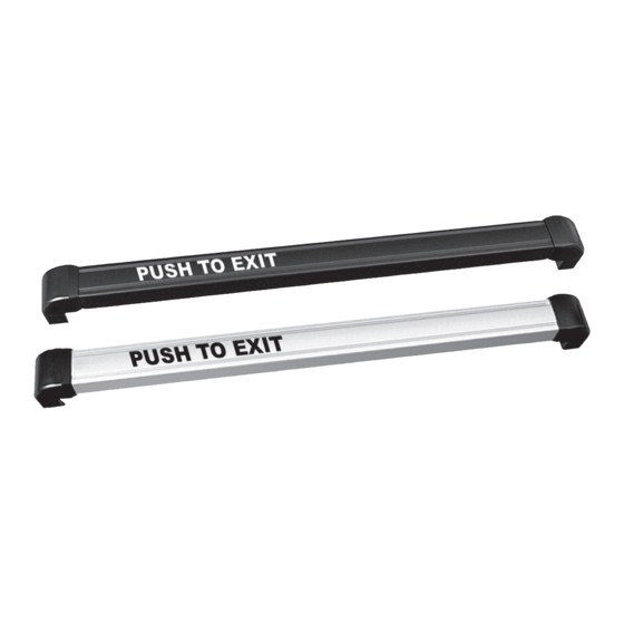
Touch Sense Bar
Installation & Operating Instructions
Description
Securitron TSB is an exit device for doors secured by magnetic
locks. The assembly consists of an aluminum bar available in
lengths to fit on standard U.S. door openings: (36", 42", and 48"),
Polycarbonate end pieces to mount the bar on the door, and
an electronic touch sensor mounted within the bar. Fasteners
for metal doors are included. For through door mounting,
please call factory for a no-charge Securitron TSB-TDM kit.
NOTE: that US type or metric fasteners are supplied depending of the version of the bar
which has been ordered. The metric version part numbers include the suffix: "M".
When the bar is touched, a relay in the sensor is tripped, releasing the lock. The
bar's sensitivity is adjustable. In the unlikely event of sensor failure, a push switch
is mounted on the back side of the bar. Depressing the switch has the same
effect as activating the sensor by touch and therefore represents built in safety
redundancy. The Securitron TSB cannot be used outside in rain conditions.
As the Securitron TSB is normally used to allow egress on an
electrically secured door, make sure that you are complying with
applicable building codes for your area. Check with your local
building department and/or fire prevention department.
Mounting Hole Marking
1
PLAN AND MARK the mounting hole positions. Be
sure that you have the correct length bar for the door.
2
REMOVE the screws that secure the end caps on both
ends of the bar. If it appears that the bar is longer than
it should be for the door, see Cutting Instructions.
3
MAKE NOTE which end has the sensor (circuit board)
in it. This is the end that should be mounted on
the hinge side for easiest wire exit from the door.
A template located at the end of this instruction
manual has been provided, although it is generally
preferable to hold the bar in position and use it as a
"self-template." The templates are particularly valuable
if door preparation is to be done in advance. In setting
your mounting holes, there are three concerns:
• They must be level or the bar will be tilted.
• They must be the correct distance apart.
• They must be correctly placed "left/right" on the door.
Leveling is best done by use of a carpenter's level.
If one is not available, measure from the mounting
hole positions on each edge of the door to the
door bottom. This is not as effective as it assumes
that the door is level which is not always true.
NOTE: In general, US building codes require the height of
the bar above the door bottom to be between 30" and 44".
TSB
®
If the bar is used as its own template, you
will automatically get correct separation
between the mounting holes.
NOTE: If you use the templates, there is a line drawn
on each template which must line up with the outer
edge of the plastic end pieces on the bar. After you've
mounted the templates, hold up the bar to make sure
the end piece lines up to get the correct distance.
Left/right placement on the door is an important
point. In most installations, the bar should be centered
on the door. This produces the most attractive result.
However, if the door has a vertical door stop on the
edge that swings open, you may need to shift the bar
somewhat towards the hinge side to avoid scraping
the stop when the door opens. You should always
experimentally position the bar on the door and
open the door to see that there is no interference.
Finally, if the installation is on an aluminum frame glass
door, make sure you don't position the bar so that the
mounting screws go into the glass. On standard doors,
keeping the mounting holes at least 3/4" (19 mm)
from the inner edge of the aluminum will be safe.
Recommended Tools
• Medium, Small Phillips Drivers
• Drill Motor
• 1/4", 3/8", 1/8" Drill Bits
• Wire Cutter/Stripper
• Volt/Ohm Meter
• Crimp Connectors And Pliers
1 of 8
Advertisement
Table of Contents

Subscribe to Our Youtube Channel
Related Manuals for Assa Abloy Securitron TSB


Summary of Contents for Assa Abloy Securitron TSB
- Page 1 The Securitron TSB cannot be used outside in rain conditions. • 1/4", 3/8", 1/8" Drill Bits As the Securitron TSB is normally used to allow egress on an • Wire Cutter/Stripper electrically secured door, make sure that you are complying with applicable building codes for your area.
- Page 2 NOTE: The Securitron Touch Sense Bar may not be used on a fire Nearly all North American commercial doors are this rated door that requires a fire rated latch (the Securitron TSB thickness. If the doors you are working on are different,...
- Page 3 THROUGH BOLT + SEX BOLT MOUNTING methods depending on door type. Using longer 3-1/2" (90 mm) machine screws with the sex bolts supplied in the Securitron TSB-TDM kit. You should have Metal Door already drilled 1/4" (6 mm) holes through the door.
-
Page 4: Electrical Specifications
Electrical Specifications The Securitron TSB has 6 colored wires which are for sensor power and DPST relay output: Red + DC Power Power Supply: Black – DC Power Voltage – 12/24 VDC White Relay Common, Pole 1 Current – 50 milliamps at rest (not being touched) and... - Page 5 Use of the REX input for exit Securitron TSB because of its two pole relay. The has two benefits: you pick up timed exiting and also in Securitron TSB’s NC contacts are used to break power...
-
Page 6: Sensor Replacement
Electric Lock Selection Electric lock selection is important to obtain best possibility of jamming and thereby denying egress. The results from the Securitron TSB. The product allows Magnalock also has internal electronics which allow it silent and immediate egress without the mechanical to release very rapidly. -
Page 7: Troubleshooting
Securitron TSB-3 Template Back Troubleshooting PROBLEM SOLUTION • To monitor operation of the bar, it is quite easy to see the red LED light indicator and hear the relay click when the bar is touched. • If the red LED does not turn on and you don’t hear a click, try the backup switch. If the door does not release from the backup switch, it is almost certain that the overall wiring of the installation is at fault. -
Page 8: Warranty
For information on warranty coverage and replacement options, please visit assaabloyesh.com/warranty Patent pending and/or patent www.assaabloydss.com/patents Copyright © 2021, Hanchett Entry Systems, Inc., an ASSA ABLOY Group company. techsupport.esh@assaabloy.com | assaabloyesh.com All rights reserved. Reproduction in whole or in part without the express written 800 626 7590 | 10027 S.
Need help?
Do you have a question about the Securitron TSB and is the answer not in the manual?
Questions and answers