Table of Contents
Advertisement
Quick Links
Instructions - Parts
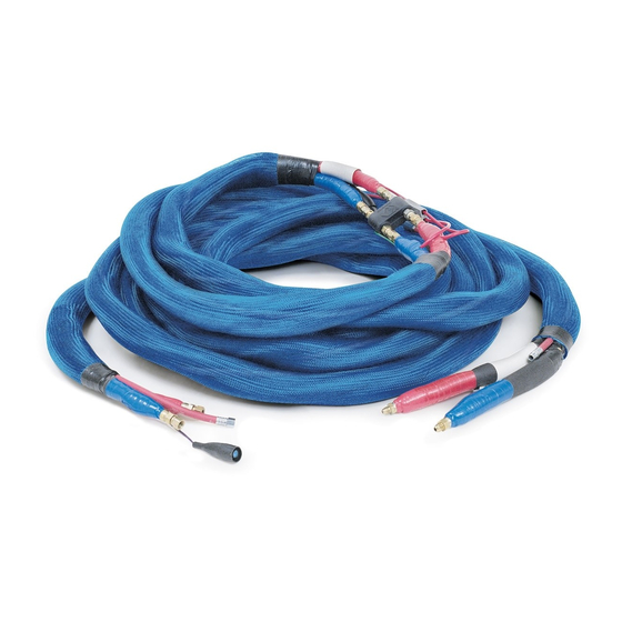
Power-Lock
Heated Hose
For use with plural component proportioners. Not for use in explosive
atmospheres.
See page 3 for Maximum Fluid Working Pressure
130 psi (0.9 MPa, 9 bar) Maximum Air Working Pressure
180°F (82°C) Maximum Hose Operating Temperature
Important Safety instructions.
Read all warnings and instructions in this manual.
Save these instructions. See page 3 for a list of
part numbers.
™
309572S
TI12157a
Advertisement
Table of Contents

Subscribe to Our Youtube Channel
Related Manuals for Graco Gusmer Power-Lock 246045


Summary of Contents for Graco Gusmer Power-Lock 246045
- Page 1 Instructions - Parts ™ Power-Lock Heated Hose 309572S For use with plural component proportioners. Not for use in explosive atmospheres. See page 3 for Maximum Fluid Working Pressure 130 psi (0.9 MPa, 9 bar) Maximum Air Working Pressure 180°F (82°C) Maximum Hose Operating Temperature Important Safety instructions.
-
Page 2: Table Of Contents
Connect 261670 FTS ....14 Graco Phone Numbers ..... 24 Check Hoses for Leaks . -
Page 3: Power-Lock Hose Bundle Part Numbers
Power-Lock Hose Bundle Part Numbers Power-Lock Hose Bundle Part Numbers You need at least one 50 ft (15.2 m) main hose, one fluid temperature sensor (FTS), and one whip hose or one wire harness jumper (part no. 15C517) to make a complete heated hose assembly. -
Page 4: Fluid Temperature Sensor (Fts)
Power-Lock Hose Bundle Part Numbers Fluid Temperature Sensor (FTS) Part No. Max. Fluid Pressure (Series) Fittings Description psi (MPa, bar) 261669 (A) JIC to JIC (See pg. 18 for Fluid Temperature Sensor (for heated standard systems) 5000 (34.5, 345) fitting detail) 261670 (A) JIC to NPT (See pg. - Page 5 Power-Lock Hose Bundle Part Numbers JIC Fittings Max Fluid Pressure “A” “B” Length Replaced inlet (f)/ inlet (f)/ (MPa, bar) ft (m) in. (mm) Description Old Part outlet (m) outlet (m) 2 Component Whip Hoses - Individual Insulation with Air Hose 2000 10 (3) 1/4 (6)
-
Page 6: Warnings
Warnings Warnings Warning Skin Injection Hazard High-pressure fluid from gun, hose leaks, or ruptured components will pierce skin. This may look like just a cut, but it is a serious injury that can result in amputation. Get immediate surgical treatment. •... - Page 7 Misuse can cause serious injury or death. • For professional use only. • Use equipment only for its intended purpose. Call your Graco distributor for information. • Read manuals, warnings, tags, and labels before operating equipment. Follow instruc- tions. •...
-
Page 8: Installation
Installation Installation Description Set Transformer Wire Taps Transformer tap wire connections vary WARNING depending on proportioner and length of heated hose. See proportioner operation man- ual for further information. Some models are This hose must be used with an FTS and automatic and have no user-set taps. -
Page 9: Connect Whip Hose To Gun Or Gun Manifold
Installation Connect Whip Hose to Gun or Gun Manifold For best whip hose flexibility, assemble whip hose to gun or gun manifold as instructed. 1. Assemble A and B component hoses to 2. Tighten fittings to A and B component gun or gun manifold fittings as shown in hoses. -
Page 10: Connect Heated Hoses
Installation Connect Heated Hoses 3. Connect air hoses (C). WARNING Read warnings, pages 6 and 7. 1. Lay heated hoses end to end, matching the color coding. Red for component A (ISO), blue for component B (RES). TI2682B 4. Connect electrical wires. a. - Page 11 Installation a. Ensure strip length is correct by fitting a. Insert one wire from heated hose into ferrule over exposed wire. Ferrule connector. Ensure that ferrule is mating should be flush with wire end. See F with connector insert. See F .
- Page 12 Installation e. Re-torque all four setscrews to 60 in-lbs 6. Connect cables (F). Slide insulator sleeves over connection. Leave slack (G) in cables (6.78 N•m). as stress relief to prevent cable failure. When torqued to 60 in-lbs (6.78 N•m) setscrews will be approximately flush with connector.
-
Page 13: Hose
Installation Connect 261669 FTS and Heated Dual Whip Hose 4. Connect fluid hoses to FTS (J). CAUTION To prevent damage to probe, do not kink or To use 1/2 in. (13 mm) ID fluid hoses, excessively bend hose. Do not coil hose remove the adapters from the propor- tighter than the minimum bend radius of 3 ft tioner fluid manifold and install them in... -
Page 14: Connect 261670 Fts
Installation Connect 261670 FTS 3. Connect fluid hoses to FTS (J). CAUTION Do not coil hose tighter than the minimum To use 1/2 in. (13 mm) ID fluid hoses, bend radius of 3 ft (0.9 m). Do not subject remove the adapters from the propor- hose to excessive weight, impact, or other tioner fluid manifold and install them in abuse. -
Page 15: Check Hoses For Leaks
Installation Check Hoses for Leaks 2. For spray guns, close fluid valves on gun fluid manifold. Remove manifold from gun, 1. Grease with Fusion grease and connect see gun manual. Connect fluid whip hoses fluid hoses to proportioner fluid manifold to manifold. -
Page 16: Protective Covering
Installation Protective Covering 3. Install protective cover (see Accessories, page 23), or wrap hose bundle with duct 1. Wrap all fluid hose connections with electri- tape to protect foam. cal tape. 4. For hoses that include a protective scuff cover, unroll excess cover over hose and electrical connections. -
Page 17: Operation
Operation Operation 3. Connect to spray gun. See gun manual. 4. Connect whip air hose to gun air inlet if WARNING equipped. See gun manual. 5. Follow setup, startup, and operation proce- dures in proportioner manual. Read warnings, pages 6 and 7. Fluid Temperature Sensor Do not operate a coiled hose. -
Page 18: Parts
Parts Parts Using 261669 Fluid Temperature Sensor (JIC to JIC fittings) Heated Fluid Hose Whip Hose Fluid Temperature Sensor TI9581B Ref. Part Description Ref. Part Description chart 6, HOSE, whip chart 1, HOSE, component A (ISO) page 20 page 20 15B280 HOSE, whip, air;... -
Page 19: Using 261670 Fluid Temperature Sensor (Jic To Npt Fittings)
Parts Using 261670 Fluid Temperature Sensor (JIC to NPT fittings) Heated Fluid Hose Fluid Temperature Sensor TI2684D Ref. Part Description Ref. Part Description 117506 . SWIVEL; 1/4 npt(m) x #6 JIC (f) chart 1, HOSE, component A (ISO) 157705 . SWIVEL; 1/4 npt(m) x 3/8 page 20 npsm(f) chart 2,... - Page 20 Parts Install new hose in bundle, wrapping around See the tables on pages 3 and 4 for fitting other fluid hose and air hose. Connect fluid sizes. hoses, see page 10. Chart for Ref. No. 1, Single Hardener (ISO) Connect electrical wire from new hose into Hose connectors (12).
-
Page 21: 15F144 Hose Wire Jumper
Parts 15F144 Hose Wire Jumper Install as follows: Use the 15F144 Hose Wire Jumper to heat WARNING only the major volume hose, in a wide ratio system. To build one complete 50 ft single side heated Read warnings, pages 6 and 7. hose bundle, order the following parts: Hoses (101 and 105) must be sized and pressure rated to meet the requirements of... - Page 22 Parts 7. Connect 261670 FTS, page 14. 11. Set transformer wire taps, using the follow- ing table. Transformer tap wire connections 8. Install whip hose and gun. Ensure that gun vary depending on length of heated hose. is grounded. See proportioner operation manual for fur- ther information.
-
Page 23: Technical Data
Technical Data Technical Data Accessories Category Data Scuff Guard Maximum See page 3 Fluid Working Use to keep hose clean and protect it from Pressure damage. Maximum 130 psi (0.9 MPa, 9 bar) Air Working Part Description Pressure 256735 7 ft (2.1 m) braided polyester Maximum 180°F (82°C) mesh. -
Page 24: Warranty
With the exception of any special, extended, or limited warranty published by Graco, Graco will, for a period of twelve months from the date of sale, repair or replace any part of the equipment determined by Graco to be defective.
Need help?
Do you have a question about the Gusmer Power-Lock 246045 and is the answer not in the manual?
Questions and answers