Table of Contents
Advertisement
Quick Links
Repair - Parts
309574C
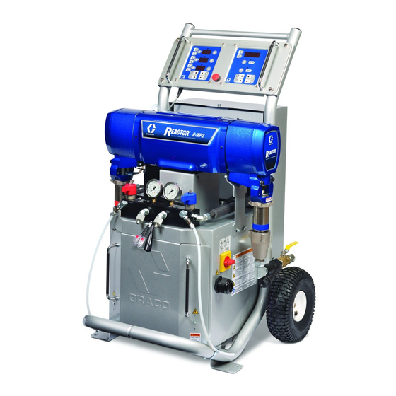
Electric, Heated, Plural Component
Proportioner
For spraying polyurethane foam and polyurea coatings.
Not for use in explosive atmospheres.
See Models on page 3.
TI3764a-1
Graco Inc. P.O. Box 1441 Minneapolis, MN 55440-1441
Copyright 2003, Graco Inc. is registered to I.S. EN ISO 9001
Advertisement
Table of Contents

Related Manuals for Graco Reactor E Series


Summary of Contents for Graco Reactor E Series
- Page 1 Electric, Heated, Plural Component Proportioner For spraying polyurethane foam and polyurea coatings. Not for use in explosive atmospheres. See Models on page 3. TI3764a-1 Graco Inc. P.O. Box 1441 Minneapolis, MN 55440-1441 Copyright 2003, Graco Inc. is registered to I.S. EN ISO 9001...
-
Page 2: Table Of Contents
Graco Standard Warranty ....62 Graco Phone Numbers ..... 62... -
Page 3: Models
Models Models E SERIES Full Load Flow Output per Maximum Fluid Part No., Voltage Peak System Heater lb/min Cycle (A + B) Working Pressure Series Model (phase) Amps* Watts** Watts (kg/min) gal. (liter) psi (MPa, bar) 246025, C E-20 230V 11,100 6,000 20 (9) -
Page 4: Related Manuals
Related Manuals Related Manuals Manual Conventions ™ Warning The following manuals are shipped with the Reactor ™ Proportioner and the Fusion Spray Gun. Refer to these manuals for detailed equipment information. WARNING Order Part No. 15B535 for a compact disk of Reactor manuals translated in several languages. -
Page 5: Warning
Warning WARNING INJECTION HAZARD High-pressure fluid from gun, hose leaks, or ruptured components will pierce skin. This may look like just a cut, but it is a serious injury that can result in amputation. Get immediate medical attention. • Do not point the gun at anyone or at any part of the body. •... - Page 6 Misuse can cause serious injury or death. • For professional use only. • Use equipment only for its intended purpose. Call your Graco distributor for information. • Read manuals, warnings, tags, and labels before operating equipment. Follow instructions. • Check equipment daily. Repair or replace worn or damaged parts immediately.
-
Page 7: Before Beginning Repair
Before Beginning Repair Before Beginning Flushing Repair WARNING WARNING Read warnings, page 5. Flush equipment only in a well-ventilated area. Do not spray flammable fluids. Do not turn on heaters while flushing with flammable sol- Repairing this equipment requires access to parts vents. -
Page 8: Pressure Relief Procedure
Pressure Relief Procedure Pressure Relief 4. Turn PRESSURE RELIEF/SPRAY valves (SA, SB) to PRESSURE RELIEF. Route fluid to waste con- Procedure tainers or supply tanks. Ensure gauges drop to 0. 1. Relieve pressure in gun and perform gun shutdown procedure. See gun manual. 2. -
Page 9: Temperature Control Diagnostic Codes
Temperature Control Diagnostic Codes Temperature Control Diagnostic Codes Temperature control diagnostic codes E01 through E05 These alarms turn off heat. Turn main power OFF appear on temperature display. then ON to clear. Code Code Name Alarm Zone Corrective Action page High fluid temperature Individual High hose current... -
Page 10: E01: High Fluid Temperature
Temperature Control Diagnostic Codes E01: High fluid temperature E04: FTS or thermocouple not connected a. Check connections between temperature control board and heater overtemperature switches, a. Check FTS operation by connecting directly to page 36. Reactor. b. Check temperature sensors, page 35. b. -
Page 11: Motor Control Diagnostic Codes
Motor Control Diagnostic Codes Motor Control Diagnostic Codes Motor control diagnostic codes E21 through E29 appear Alarms can also be cleared, except for code 23, on pressure display. by pressing There are two types of motor control codes: alarms and warnings. -
Page 12: E21: No Component A Transducer
Motor Control Diagnostic Codes E21: No component A E24: Pressure imbalance transducer A and B pressures are imbalanced. Secure bleed lines in grounded waste containers, or a. Check transducer connection J3 at motor control route back to respective component A or B sup- board, page 29. -
Page 13: E25: High Line Voltage
Motor Control Diagnostic Codes E25: High line voltage E28: High current in motor Supply voltage too high. Check Reactor voltage a. Short on motor control board. Replace board, requirements, page 61. page 28. E26: Low line voltage b. Replace motor, page 27. Supply voltage too low. -
Page 14: Troubleshooting
Troubleshooting Troubleshooting PROBLEM CAUSE SOLUTION Reactor does not operate. No power. Plug in power cord. Turn main power ON Turn circuit breakers ON, page 26. Red stop button circuit open. Check button connections. See page 40 and electrical diagrams. Motor does not operate. Loose connections. - Page 15 Troubleshooting PROBLEM CAUSE SOLUTION No display. Main power OFF. Turn main power ON Loose display cable. Check cable connections, page 40. Both display boards failed. Check boards, replace; page 40. No temperature display. Loose display cable. Check cable connections, page 40. Failed temperature control board.
- Page 16 Troubleshooting PROBLEM CAUSE SOLUTION No heat in A or B zones Circuit breaker(s) tripped. Reset breaker CB3 or CB4, page 26. Heat turned off. Press zone keys. Temperature control alarm. Check temperature displays for diag- nostic code, page 9. Defective heater. Replace, page 34.
- Page 17 Troubleshooting PROBLEM CAUSE SOLUTION No hose heat Loose hose electrical connections. Check connections. Repair as neces- sary. Circuit breakers tripped. Reset breakers (CB1 or CB2), page Hose zone not turned on. Press zone key. A and B temperature setpoints too Check.
-
Page 18: Repair
Repair Repair Pump Removal See manual 309577 for pump repair instructions. 6. Turn main power OFF . Disconnect power supply. 1. Shut off , and heat zones. Steps 7-9 apply to pump A. See F . 1. To discon- 2. Flush pump, page 7. nect pump B, go to steps 10 and 11. - Page 19 Repair TI3765a-1 TI3765a-2 . 1. Disconnect Pump A . 2. Disconnect Pump B 309574C...
-
Page 20: Pump Installation
Repair Pump Installation 3. Turn main power OFF . Disconnect power WARNING supply. Steps 4-7 apply to pump B. See F . 3. To recon- Pump rod and connecting rod move during operation. nect pump A, go to step 8 on page 21. Moving parts can cause serious injury such as pinch- ing or amputation. - Page 21 Repair Steps 8-13 apply to pump A only. See F . 4. 10. Wet-cup has three 1/8 npt ports. One is inaccessi- ble; note location. Back pump out and install plug in that port. 8. Ensure locknut (G) is screwed on pump with flat side up, and finger guard is placed in window of bearing housing (M).
-
Page 22: Drive Housing
Repair Drive Housing Removal The A side drive housing includes cycle counter switch (321). If replacing this housing, remove pins (P) and switch. Reinstall pins and switch on new drive housing. Switch wires connect to J10 1. Turn main power OFF . - Page 23 Repair 306B 306A Crankshaft must be in line with crankshaft at other end of motor. TI3152A . 5. Drive Housing 309574C...
-
Page 24: Motor Brushes
Repair Motor Brushes 5. Loosen terminal screw (R). Pull away brush lead (L), being careful motor lead terminal (T) remains in place. Remove and discard brush (B). Brush Removal Replace brushes worn to less than 1/2 in. (13 mm). Brushes wear differently on each side of motor;... - Page 25 Repair 2. Slide terminal (L) under terminal screw (R). Make 4. Install spring clip (C) and push in until hooks (H) sure motor lead terminal (T) is still connected at catch slots in housing. Incorrect installation may jam screw. Tighten screw. clip 01227-2 01227-6...
-
Page 26: Circuit Breaker Module
Repair Circuit Breaker Module Table 1: Circuit Breakers, see F Ref. No. Size Component 50 A Hose/Transformer 1. Turn main power OFF . Disconnect power Secondary Side supply. 817A 20 A Transformer Primary 804A 25 or 40 A* Heater A WARNING 804B 25 or 40 A*... -
Page 27: Electric Motor
Repair Electric Motor c. Unplug 3-pin connector J7 from board. d. Thread cables through top of cabinet to free Removal motor. 1. Turn main power OFF . Disconnect power CAUTION Motor is heavy. Two people may be required to lift. supply. -
Page 28: Motor Control Board
Repair Motor Control Board 8. Set DIP switch (SW2) on new board. See below for factory settings. See F . 7 for location on board. Motor control board has one red LED (D11 for • Switches 1 and 4: not used, leave OFF. 245980, D7 for 245981). - Page 29 Repair 245980 Motor Control, for E-20 and E-XP1 TI3153A-1 245981 Motor Control, for E-30 and E-XP2 Apply 110009 thermal heatsink compound to mating surfaces. TI2576A-1 . 7. Motor Control Board 309574C...
-
Page 30: Transducers
Repair Transducers 4. Disconnect transducer cable at board; transducer A from J3, transducer B from J8. Swap connections and check if diagnostic code follows, page 12. 5. If transducer fails test, thread cable through top of 1. Turn main power OFF . -
Page 31: Fan
Repair 2. Relieve pressure, page 8. 3. Check fuses (F) at left of breaker module, F . 9. 1. Turn main power OFF . Disconnect power Replace if blown. If good, continue with step 4. supply. 4. Refer to electrical diagrams. Disconnect fan wires from fuses (F). -
Page 32: Temperature Control Board
Repair Temperature Control Board 2. Relieve pressure, page 8. 3. Refer to electrical diagrams. Temperature control board is on left side inside cabinet. Temperature control board has seven green LEDs. Power must be on to check. See F . 7 for 4. - Page 33 Repair Apply 110009 thermal heatsink compound to mating surfaces. TI2572a . 10. Temperature Control Board 309574C...
-
Page 34: Heater
Repair Heater Heater Element 1. Turn main power OFF . Disconnect power supply. 2. Relieve pressure, page 8. WARNING Read warnings, page 6. Wait for heaters to cool before repairing. 3. Wait for heaters to cool. 4. See F . 11. Remove tape and wire connector (63, not shown), and disconnect heater element wires (W) from heater wire harness. - Page 35 Repair Temperature Sensor c. Push in sensor so tip (T) contacts heater ele- ment (207), avoiding mixer (202). d. Tighten ferrule nut (N), holding sensor (T) 1. Turn main power OFF . Disconnect power against heater element. supply. 9. Route wires into cabinet and thread into bundle as before.
- Page 36 Repair Overtemperature Switch 3. Wait for heaters to cool. 4. Disconnect one leadwire from overtemperature switch (208), F . 12. Test across switch with ohm- 1. Turn main power OFF . Disconnect power meter. Resistance must be approximately 0 ohms. supply.
-
Page 37: Heated Hose
Repair Heated Hose 3. Disconnect FTS cable (F) at Reactor, F . 13. 4. Test with ohmmeter between pins of cable connec- tor. Refer to the heated hose manual 309572 for hose replacement parts. Check Hose Connectors Pins Result 1 to 2 approximately 35 ohms per 50 ft (15.2 m) of hose, plus approximately 10 ohms for FTS 1. -
Page 38: Fluid Temperature Sensor (Fts)
Repair Fluid Temperature Sensor 6. Disconnect FTS from whip hose (W) and fluid hoses (A, B). (FTS) 7. Remove ground wire (K) from ground screw on underside of FTS. Test/Removal 8. Remove FTS probe (H) from component A (ISO) side of hose. 1. - Page 39 Repair TI2684a1 . 14. Fluid Temperature Sensor and Heated Hoses 309574C...
-
Page 40: Display Module
Repair Display Module If replacing both displays, label temperature dis- play cables TEMP and pressure display cables PUMP before disconnecting. Temperature and Pressure Displays 7. Disconnect cable connectors J1 and J13 from back of temperature display (401) or pressure display CAUTION (402). - Page 41 Repair Apply medium strength thread sealant. TI2574A Detail of Membrane Switches and Display Boards Pressure Display Temperature Display 402c 402a 402b 401c 401a 401b TI3172a . 15. Display Module 309574C...
- Page 42 Repair Red Stop Button 2. Relieve pressure, page 8. 3. Refer to electrical diagrams. CAUTION 4. Put on static conductive wrist strap. Before handling board, put on a static conductive wrist strap to protect against static discharge which can 5. Remove screws (409, 410) and cover (404), F .
-
Page 43: Parts
Parts Parts Reactor Assembly (Model E-XP1 Shown) 57, 38 TI3764a-1 23, 38 TI3764a-2 41, 102 7, 12, 41 113, 119, 114 110, 118 13, 26, 35 109, 111, 112 TI3765a-2 66, 66a 309574C... - Page 44 Parts 29, 42 76, 78, 74, 75 29, 42 39, 73 TI2605A 309574C...
-
Page 45: Reactor Assembly
Parts Reactor Assembly Parts that Vary by Model Use the tables on this page and the next page to find parts that vary by model. Find the ref. no. of part in left column, and Reactor model in top row. Intersection is correct part no. See page 47 for parts common to all models. - Page 46 Parts Reactor Models Ref. 246024 246025 246026 246028 246029 246030 246031 246032 246033 246034 246035 246036 No. Description E-XP1 E-20 E-30 E-XP2 E-XP1 E-20 E-30 E-XP2 E-XP1 E-20 E-30 E-XP2 LABEL, warning 198278 198278 198278 198278 198278 198278 CABLE, har- 15B385 15B385 15B385 15B385 15B385 15B385...
- Page 47 Parts Common Parts Ref. Ref. Part No. Description Part No. Description 246895 COVER, heater, back 245954 FRAME; page 48 15B798 COVER, heater, front 245974 DISPLAY; page 52 15B679 LABEL, warning 245979 CONTROL, temperature; page 53 113505 NUT, hex, keps; 10-24 246154 MANIFOLD, fluid;...
-
Page 48: Reactor Frame
Parts Reactor Frame Fluid Heater 245954 Frame 245962 10.2 kW Heater, for E-30 and E-XP1 Reactor TI2512A TI2513A Ref. Ref. Part No. Description Part No. Description 246204 FRAME 15B134 HOUSING 116478 WHEEL 15B135 MIXER 101242 RING, retaining 118426 CLAMP 116477 WASHER, flat;... - Page 49 Parts 245963 7.65 kW Heater, for E-XP2 Reactor 245975 6 kW Heater, for E-20 Reactor (2 required) TI2578A TI2512A Ref. Ref. Part No. Description Part No. Description 15B134 HOUSING 15B134 HOUSING 15B135 MIXER 15B135 MIXER 118426 CLAMP 118426 CLAMP 15B133 CROSSOVER 15B132 MANIFOLD...
-
Page 50: Proportioner Module
Parts Proportioner Module 245956 Module, for E-20 and E-XP1 245957 Module, for E-30 245959 Module, for E-XP2 **310 310** 306B *307 308* 306A Detail of Cycle Counter Switch Flat side faces up. TI2511A TI3250a 309574C... - Page 51 Parts 245956 Module, for E-20 and E-XP1 245957 Module, for E-30 245959 Module, for E-XP2 Ref. Ref. Part No. Description Part No. Description 107218 SCREW, cap, socket-hd; 1/4-20 x 2-3/4 245965 MOTOR; 245956 in. (70 mm); 245956 245966 MOTOR; 245957, 245959 114686 SCREW, cap, socket-hd;...
-
Page 52: Display
Parts Display 245974 Display TI2574A 402c 402a 402b 401c 401a 401b TI3172a Ref. Ref. Part No. Description Part No. Description 15B293 GASKET 245978 DISPLAY, pressure; includes 15B292 COVER 401a-401c 15B291 PLATE 401a 246130 . BOARD, circuit 246287 HARNESS, wire, red stop button 401b 246478 . -
Page 53: Temperature Control
Parts Temperature Control 245979 Temperature Control Apply 110009 thermal heatsink compound to mating surfaces. TI2575A-1 Ref. Part No. Description 15B779 HEAT SINK 246194 BOARD, temperature control 117683 SCREW, 6-32 x 1-1/2 in. (38 mm) 117526 SPACER 104590 SCREW, machine; 6-32 x 3/8 in. (10 309574C... -
Page 54: Motor Control
Parts Motor Control 245980 Motor Control, for E-20 and E-XP1 TI3153A Apply 110009 thermal heatsink compound to mating surfaces. Ref. Part No. Description 15B297 HEAT SINK 246195 BOARD, motor control 107156 SCREW, machine; 6-32 309574C... - Page 55 Parts 245981 Motor Control, for E-30 and E-XP2 Apply 110009 thermal heatsink compound to mating surfaces. Motor harness (609) plugs in here. TI2576A Ref. Part No. Description 15B297 HEAT SINK 246196 BOARD, motor control 104590 SCREW, machine; 6-32 x 3/8 in. (10 mm) 117526 SPACER 117683...
-
Page 56: Fluid Manifold
Parts Fluid Manifold 246154 Fluid Manifold Apply 113500 thread lock (blue). Torque to 355-395 in-lb (40.1-44.6 N•m). Apply PTFE tape or thread sealant to tapered threads. Torque to 175-195 in-lb (19.8-22.0 N•m). Lubricate ends of spring when assembling. Assemble valves (702) and handles (709) with handles facing away from each other. -
Page 57: Circuit Breaker Modules
Parts Circuit Breaker Modules 230V, 3 Phase Circuit Breaker Modules For wiring and cable connections, refer to electri- cal diagrams supplied. See page 60 for parts list. Part No. 246087 (E-20, E-30, E-XP1) 803, 814, Ref. No. 92 not included with module. Order separately, see page 46. - Page 58 Parts 230V, 1 Phase Circuit Breaker Modules For wiring and cable connections, refer to electri- cal diagrams supplied. See page 60 for parts list. Part No. 246090 (E-20, E-30, E-XP1) 803, 814, Ref. No. 92 not included with module. Order separately, see page 46. 1070 1090 1880...
- Page 59 Parts 380V, 3 Phase Circuit Breaker Modules For wiring and cable connections, refer to electri- cal diagrams supplied. See page 60 for parts list. Part No. 246096 (E-20, E-30, E-XP1) Ref. No. 92 not included with module. 803, Order separately, see page 46. 814, 1070 1090...
- Page 60 Parts Circuit Breaker Modules Parts List Breaker Modules 246087 246090 246096 230V, 3 θ 230V, 1 θ 380V, 3 θ Ref. 246087 (E-30 246089 246090 (E-30 246092 246096 (E-30 246098 230V, 3 θ 230V, 3 θ 230V, 1 θ 230V, 1 θ 380V, 3 θ...
-
Page 61: Technical Data
Technical Data Technical Data Category Data Maximum Fluid Working Pressure Models E-20 and E-30: 2000 psi (14 MPa, 140 bar) Model E-XP1: 2500 psi (17.2 MPa, 172 bar) Model E-XP2: 3500 psi (24.1 MPa, 241 bar) Maximum Fluid Temperature 190°F (88°C) Maximum Output Model E-20: 20 lb/min (9 kg/min) Model E-30: 30 lb/min (13.5 kg/min) -
Page 62: Graco Standard Warranty
Graco distributor to the original purchaser for use. With the exception of any special, extended, or limited warranty published by Graco, Graco will, for a period of twelve months from the date of sale, repair or replace any part of the equipment determined by Graco to be defective.
Need help?
Do you have a question about the Reactor E Series and is the answer not in the manual?
Questions and answers