Table of Contents
Advertisement
Quick Links
This manual is made with 100% recycled paper.
EN AR
DB68-04191A(1)
DVM S NASA_Global 4-WC_사우디향_IM_EN_04191A.indd 1
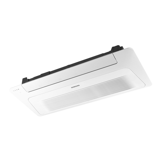
Air Conditioner
installation manual
imagine
the possibilities
Thank you for purchasing this Samsung product.
To receive more complete service, please register
your product at
www.samsung.com/register
Cassette Type Series
Slim 1 Way cassette : AM✴✴✴FN1DCH✴
2 Way cassette : AM✴✴✴FN2DCH✴
4 Way cassette : AM✴✴✴FN4DCH✴
2013-11-05 오전 11:30:11
Advertisement
Table of Contents

Related Manuals for Samsung AM FN1DCH Series


Summary of Contents for Samsung AM FN1DCH Series
- Page 1 4 Way cassette : AM✴✴✴FN4DCH✴ Air Conditioner installation manual This manual is made with 100% recycled paper. imagine the possibilities Thank you for purchasing this Samsung product. To receive more complete service, please register your product at www.samsung.com/register EN AR DB68-04191A(1) DVM S NASA_Global 4-WC_사우디향_IM_EN_04191A.indd 1...
-
Page 2: Table Of Contents
X This manual explains how to install an indoor unit with a split system with two SAMSUNG units. The use of other types of units with different control systems may damage the units and invalidate the warranty. The manufacturer shall not be responsible for damages arising from the use of non compliant units. - Page 3 X Do not place containers with liquids or other objects on the unit. X All the materials used for the manufacture and packaging of the air conditioner are recyclable. X The packing material and exhaust batteries of the remote control(optional) must be disposed of in accordance with current laws.
- Page 4 Safety Precautions • Make sure that you earth the cables. CAUTION Do not connect the earth wire to the gas pipe, water pipe, lighting rod or telephone wire. If earthing is not complete, electric shock or fire may occur. • Install the circuit breaker. If the circuit breaker is not installed, electric shock or fire may occur.
-
Page 5: Accessories
Accessories The following accessories are supplied with the indoor unit. The type and quantity may differ depending on the specifications. AM✴✴✴FN1DCH✴ / AM✴✴✴FN2DCH✴ Installation Pattern sheet Insulation drain Flexible hose Insulation user manual manual AM✴✴✴FN4DCH✴ Insulation Cable-tie Drain hose Installation Clamp Pattern sheet user manual... - Page 6 Selecting the Installation Location Space Requirements for Indoor Unit AM✴✴✴FN1DCH✴ / AM✴✴✴FN2DCH✴ AM✴✴✴FN4DCH✴ • The units must be installed according to distances declared, in order to permit accessibility from each CAUTION side, either to guarantee correct operation of maintenance or repairing products. The unit’s parts must be reachable and removable completely under safety condition (for people or things).
- Page 7 Insulation Guide 2 Way cassette (Unit : mm) Thickness: more than 10mm Indoor unit 5.6~7.1kW 880x185 880x185 570x185 570x185 880x570 (890x230x575) • Insulate the end of the pipe and some curved area by using separate insulator. DVM S NASA_Global 4-WC_사우디향_IM_EN_04191A.indd 7 2013-11-05 오전...
- Page 8 Selecting the Installation Location Dimension of the indoor unit AM✴✴✴FN1DCH✴ (Unit : mm) 1150 (Suspension position) 1035.8 (Ceiling opening) Drain hole Celling 1198 Name Description Liquid pipe connection ø6.35 Gas pipe connection ø12.70 Drain pipe connection OD : ø32, ID : ø26 Power supply connection Air discharge grille Air suction grille...
- Page 9 AM✴✴✴FN2DCH✴ (Unit : mm) 136.5 1030 Name Description ✴✴056✴✴ : ø6.35 Liquid pipe connection ✴✴071✴✴ : ø9.52 ✴✴056✴✴ : ø12.7 Gas pipe connection ✴✴071✴✴ : ø15.88 Drain pipe connection OD : ø32, ID : ø26 Power supply connection Air discharge grille Air suction grille DVM S NASA_Global 4-WC_사우디향_IM_EN_04191A.indd 9 2013-11-05 오전...
- Page 10 Selecting the Installation Location AM✴✴✴FN4DCH✴ (Unit : mm) 890~910 (Celling opening) 735 (Suspension position) Sub duct connection MODEL ✴✴045✴✴ ✴✴071✴✴ ✴✴128✴✴ ✴✴112✴✴ ✴✴056✴✴ ✴✴090✴✴ ✴✴140✴✴ Liquid pipe connection ø6.35 ø9.52 Gas pipe connection ø12.7 ø15.88 Drain Hose connection OD : ø32, ID : ø26 DVM S NASA_Global 4-WC_사우디향_IM_EN_04191A.indd 10 2013-11-05 오전...
-
Page 11: Indoor Unit Installation
Indoor Unit Installation It is recommended to install the Y-joint before installing the indoor unit. 1. Place the pattern sheet on the ceiling at the spot where you want to install the indoor unit. • Since the diagram is made of paper, it may shrink or stretch slightly due to temperature or humidity. -
Page 12: Purging The Unit
Indoor Unit Installation 6. Adjust the height of the indoor unit by using the gauge of dimensions. • You should adjust the gauge of dimensions and the pattern sheet to fit the cutting dimensions of ceiling. • Make sure that the indoor unit is installed at a level if the indoor unit slants too much, there can be water leaks. AM✴✴✴FN1DCH✴... -
Page 13: Connecting The Refrigerant Pipe
Connecting the Refrigerant Pipe There are two refrigerant pipes of differing diameters: • A smaller one for the liquid refrigerant • A larger one for the gas refrigerant • The inside of copper pipe must be clean & has no dust. 1. -
Page 14: Cutting/Flaring The Pipes
Cutting/Flaring the Pipes 1. Make sure that you prepared the required tools. (pipe cutter, reamer, flaring tool and pipe holder) 2. If you want to shorten the pipe, cut it using a pipe cutter ensuring that the cut edge remains at 90° with the side of the pipe. There are some examples of correctly and incorrectly cut edges below. - Page 15 5. Check if you flared the pipe correctly. There are some examples of ncorrectly flared pipes below. Correct Inclined Damaged Surface Cracked Uneven Thickness 6. Align the pipes and tighten the flare nuts first manually and then with a torque wrench, applying the following torque. Connection Torque Flare Outer diameter...
-
Page 16: Performing Leak Test & Insulation
Performing Leak Test & Insulation Leak test LEAK TEST WITH NITROGEN (before opening valves) In order to detect basic refrigerant leaks, before recreating the vacuum and recirculating the R-410A, it’s responsible of installer to pressurize the whole system with nitrogen (using a pressure regulator) at a pressure above 4.1MPa (gauge). - Page 17 5. Select the insulation of the refrigerant pipe. • Insulate the gas side and liquid side pipe referring to the thickness according to the pipe size. • Indoor temperature of 30°C and humidity of 85% is the standard condition. If installing in a high humidity condition, use one grade thicker insulator by referring to the table below. If installing in an unfavorable conditions, use thicker one.
- Page 18 Performing Leak Test & Insulation Refrigerant pipe before EEV kit and MCU or without EEV kit and MCU • You can contact the gas side and liquid side pipes but the pipes should Insulation not be pressed. Insulation • When contacting the gas side and gas side pipe, use 1 grade thicker insulator.
-
Page 19: Drain Pipe And Drain Hose Installation
Drain pipe and Drain Hose Installation Care must be taken when installing the drainpipe and drain hose for the indoor unit so that condensate water is drained correctly outside. 1. Fix the flexible hose to the drainpipe. AM✴✴✴FN1DCH✴ / AM✴✴✴FN2DCH✴ Drainpipe • The connection port of the flexible hose and PVC drainpipe must be Flexible hose... - Page 20 Drain pipe and Drain Hose Installation Drainpipe Connection 1. The drain pipe should be installed within 100mm from the flexible hose, lift up from 100mm to 550mm and lift down 20mm or more. 2. Install horizontal drainpipe with a slope of 1/100 or more and fix it by hanger space of 1~1.5m. 3.
- Page 21 Centralized Drainage 1. Install main air vent at the front of the farthest indoor unit from the main drain when installed indoor units are more than 3. 2. You may need to install individual air vent to prevent water flow back at the top of each indoor unit drainpipe. 1~1.5m Hanger Main air vent...
-
Page 22: Wiring Work
Wiring Work Power and communication cable connection 1. Before wiring work, you must turn off all power source. 2. Indoor unit power should be supplied through the breaker(MCCB, ELB) separated by the outdoor power. 3. The power cable should be used only copper wires. 4. - Page 23 Specification of electronic wire Power supply MCCB Power cable Earth cable Communication cable Max : 242V XA, 30mmA 2.5mm 2.5mm 0.75~1.5mm Min : 198V 0.1 s • Decide the capacity of ELB and MCCB by below formula. The capacity of ELB, MCCB X [A] = 1.25 X 1.1 X ΣAi ✴...
- Page 24 Wiring Work Example of Installation Total power cable length L = 100(m), Running current of each units 1[A] Total 10 indoor units were installed 10[A] 9[A] 1[A] MCCB Indoor unit1 Indoor unit2 Indoor unit10 0[m] 10[m] 20[m] 100[m] • Apply following equation. Coef×35.6×L ×i 10% of input...
- Page 25 • Select the power cable in accordance with relevant local and national regulations. • Wire size must comply with local and national code. CAUTION • For the power cable, use the grade of H07RN-F or H05RN-F materials. • You should connect the power cable into the power cable terminal and fasten it with a clamp. • The unbalanced power must be maintained within 10% of supply rating among whole indoor units.
-
Page 26: Setting An Indoor Unit Address And Installation Option
Setting an indoor unit address and installation option Set the indoor unit address and installation option with remote controller option. Set the each option separately since you cannot set the ADDRESS setting and indoor unit installation setting option at the same time. You need to set twice when setting indoor unit address and installation option. The procedure of option setting Entering mode for Option setting... - Page 27 Option setting Status 1. Setting SEG2, SEG3 option Press Low Fan button( ) to enter SEG2 value. Press High Fan button( ) to enter SEG3 value. SEG2 SEG3 Each time you press the button, … will be selected in rotation. 2.
- Page 28 Setting an indoor unit address and installation option Option setting Status 14. Setting Dry mode Press Mode button to be change to Dry mode in the OFF status. 15. Setting SEG18, SEG20 option Press Low Fan button( ) to enter SEG18 value. Press High Fan button( ) to enter SEG20 value.
- Page 29 Setting an indoor unit address (MAIN/RMC) 1. Check whether power is supplied or not. When the indoor unit is not plugged in, there should be additional Indoor Unit power supply in the indoor unit. 1(L) 2. The panel(display) should be connected to an indoor unit to receive 2(N) option.
- Page 30 Setting an indoor unit address and installation option Setting an indoor unit installation option (suitable for the condition of each installation location) 1. Check whether power is supplied or not. When the indoor unit is not plugged in, there should be additional Indoor Unit power supply in the indoor unit.
- Page 31 02 series installation option(Detailed) Option No. : 02XXXX-1XXXXX-2XXXXX-3XXXXX Option SEG1 SEG2 SEG3 SEG4 SEG5 SEG6 Use of external Explanation PAGE MODE Use of robot cleaning room temperature Use of central control FAN RPM compensation sensor Remote Controller Display Indication Details Indication Details Indication Details Indication Details Indication...
- Page 32 Setting an indoor unit address and installation option Option SEG19 SEG20 SEG21 SEG22 SEG23 SEG24 EEV Step of stopped Individual control of Heating setting Explanation PAGE unit during oil return/ Motion detect sensor a remote controller compensation defrost mode Remote Controller Display Indication Details Indication Details Indication Details...
- Page 33 05 series installation option(Detailed) Option No. : 05XXXX-1XXXXX-2XXXXX-3XXXXX Option SEG1 SEG2 SEG3 SEG4 SEG5 SEG6 (When setting SEG3) (When setting SEG3) (When setting SEG3) Use of Auto Change Standard for mode Explanation PAGE MODE Over for HR only in Standard heating temp. Standard cooling change Auto mode...
- Page 34 Setting an indoor unit address and installation option SEG 3, 4, 5, 6, 8, 9 additional information When the SEG 3 is set as “1” and follow Auto Change Over for HR only operation, it will operate as follows. Standard temp. for Temp.
- Page 35 Changing a particular option You can change each digit of set option. Option SEG1 SEG2 SEG3 SEG4 SEG5 SEG6 The tens’ digit of an The unit digit of an The option mode Explanation PAGE MODE option SEG you will option SEG you will The changed value you want to change change...
-
Page 36: Final Checks And User Tips
Final Checks and User Tips To complete the installation, perform the following checks and tests to ensure that the air conditioner operates correctly. Check the followings. • Strength of the installation site • Tightness of pipe connection to detect a gas leak • Electric wiring connections • Heat-resistant insulation of the pipe • Drainage... -
Page 37: Troubleshooting
Troubleshooting Detection of errors • If an error occurs during the operation, an LED flickers and the operation is stopped except the LED. • If you re-operate the air conditioner, it operates normally at first, then detect an error again. LED Display on the receiver &... - Page 38 Troubleshooting LED Display Abnormal condition Error code Green 1. COND mid sensor is detached E241 2. Refrigerant leakage (2nd detection) E554 3. Abnomally high temperature on Cond (2nd detection) E450 4. Low pressure s/w (2nd detection) E451 5. Abnomally high temperature on discharged air on outdoor unit (2nd E416 detection) 6.
- Page 39 LED Display Abnormal condition Error code Operation Defrost Timer Filter 1. When there is no communication between the indoor∙outdoor units E101 for 2 minutes 2. Communication error received from the outdoor unit E102 3. 3 miniute tracking error on outdoor unit E202 4.
- Page 40 DVM S NASA_Global 4-WC_사우디향_IM_EN_04191A.indd 40 2013-11-05 오전 11:30:36...
Need help?
Do you have a question about the AM FN1DCH Series and is the answer not in the manual?
Questions and answers