Samsung FH052EAMT Service Manual
Indoor/outdoor unit ceiling type
Hide thumbs
Also See for FH052EAMT:
- Owner's instructions manual (16 pages) ,
- Installation manual (22 pages)
Advertisement
Table of Contents
- 1 Table of Contents
- 2 Product Specifications
- 3 Disassembly and Reassembly
- 4 Refrigerating Cycle Diagram
- 5 Set up the Model Option
- 6 Control Specification & Troubleshooting
- 7 Exploded Views and Parts List
- 8 PCB Diagram
- 9 Wiring Diagram
- 10 Schematic Diagram
- Download this manual
See also:
Installation Manual
SERVICE
AIR CONDITIONER
CEILING TYPE AIR CONDITIONER
INDOOR UNIT
FH052EAMT
FH070EAMT
Manual
CONTENTS
OUTDOOR UNIT
UH052EAMT
UH070EAMT
Advertisement
Table of Contents
Troubleshooting

Related Manuals for Samsung FH052EAMT


Summary of Contents for Samsung FH052EAMT
-
Page 1: Table Of Contents
CEILING TYPE AIR CONDITIONER INDOOR UNIT OUTDOOR UNIT FH052EAMT UH052EAMT FH070EAMT UH070EAMT Manual SERVICE AIR CONDITIONER CONTENTS 1. Product Specifications 2. Disassembly and Reassembly 3. Refrigerating Cycle Diagram 4. Set Up the Model Option 5. Control Specification & Troubleshooting 6. Exploded Views and Parts List 7. -
Page 2: Product Specifications
1. Product Specifications 1-1 Table INDOOR UNIT FH052EAMT FH070EAMT MODEL OUTDOOR UNIT UH052EAMT UH070EAMT Btu/h 18,700 23,800 Cooling 5,500 7,000 Capacity Btu/h 20,400 26,100 Heating 6,000 7,700 Power Supply ø/V/Hz 1/220 ~ 240/50 1/220 ~ 240/50 Cooling 1,800 2,400 Power Input... - Page 3 Table(cont.) INDOOR UNIT FH052EAMT FH070EAMT MODEL OUTDOOR UNIT UH052EAMT UH070EAMT Type R410a R410a Charge 1,550 1,650 Refrigerant Adding Charge Control Elec.Expansion Valve Elec.Expansion Valve Type Slit Slit Outdoor Heat Exchanger Unit Row x Stages x Fin Pitch 2 x 28 x 1.5mm 2 x 28 x 1.5mm...
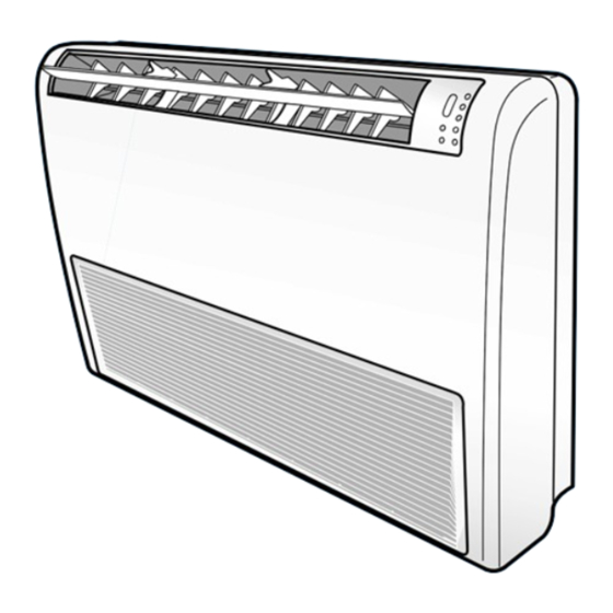
- Page 4 Air intake hole (Ø50) Wiring hole Drain hose outlet Air flow blade(up/ down) Air flow blade(right/ left) Remote control sensor Defrosting indicator Air filter Filter sign indicator Fan indicator Front grille Auto indicator Timer indicator Operation indicator On/Off button Samsung Electronics...
- Page 5 Product Specifications 1-2-2 Outdoor Unit (Unit : mm) Samsung Electronics...
-
Page 6: Disassembly And Reassembly
Procedure Remark 1) Open the grille by pressing 3 position. Electrical (center and both side) Part 2) Detach the air inlet grille. 3) Open the cover of component electrical box by removing 3 screws. (center and both side) Samsung Electronics... - Page 7 Disassembly and Reassembly Parts Procedure Remark 1) Detach the screw and untie earth Fan & Motor wire of motor. 2) Disconnect of housing of motor wire. 3) Disconnect the capacitor wire. Samsung Electronics...
- Page 8 Disassembly and Reassembly Parts Procedure Remark 4) Loosen the guard safety by removing 6 screws. 5) Detach the upper case of fan. (2EA) 6) Loosen the 4 screws what is fix the motor. 7) Detach the fan and motor assembly. Samsung Electronics...
- Page 9 9) Detach the fan. 1) Disconnect the display pcb wire as shown Drain Pan in picture. (white housing) 2) Disconnect the step motor wire as shown in picture. (blue housing) 3) Disassemble the hanger bracket by removing the 1 screw. Samsung Electronics...
- Page 10 4) Loosen the 3 screws of front side. 5) Disassemble the assembly front cover part. 6) Disconnect the step motor wire as shown in picture. 7) Detach the wire clamp fixed in base part. 8) Detach the front cover assembly completely. Samsung Electronics...
- Page 11 Procedure Remark 9) Loosen the screw what is fix with base part and drain pan. (upper side:2EA) 10) Loosen the screw what is fix with base part and drain pan. (lower side:2EA) 11) Detach the drain pan completely. Samsung Electronics...
- Page 12 3) Loosen the 2 screws shown in picture and remove plastic part. (white) 4) Loosen the 2 screws shown in picture and remove steel bracket. 5) Disassemble the 4 screws steel plate in rear side of the unit. Samsung Electronics...
- Page 13 Disassembly and Reassembly Parts Procedure Remark 6) Loosen the 2 screws as shown in picture. 7) Detach the plastic cover as shown in picture. 8) Detach the evaporator assembly. Samsung Electronics...
- Page 14 2 screws stepping motor. Display PCB 1) Loosen the 3 screws in rear side of front cover assembly as shown in picture. 2) Disassemble display PCB assembly and disconnect wire. 3) Disassemble the display PCB. Samsung Electronics...
- Page 15 6) Detach the cabi-front. Cautions When you assemble the parts, check if the each parts and component electric box are fixed firmly. Fan Motor 1) Loosen the indicating bolt screw. & 2) Disassemble the propeller fan. Propeller Fan Samsung Electronics...
-
Page 16: Refrigerating Cycle Diagram
Allowable pipe length : Max. 30m Allowable drop distance : Max. 15m 2-way valve Liquid pipe Filter Filter Expansion valve Capillary tube Heat exchanger Heat (Condensor) exchanger (Evaporator) Gas pipe 3-way valve Cooling 4-way valve Heating Accumulator Muffler Gas leak check point Compressor Samsung Electronics... -
Page 17: Set Up The Model Option
. . . repeatedly. Setting is not required if you must Push the button to set the display panel to a value which has a default. Every time you push the button, the display panel reads . . . repeatedly. Samsung Electronics... - Page 18 (If the diriring sound isn’t heard, try again pressing the ON/OFF button.) Step 5 : Unit operation test-run First, Remove the battery from the remote controller. Second, Re-insert the battery into the remote controller. Third, Press ON/OFF button( ) with the direction of remote controller for set. Samsung Electronics...
- Page 19 Set Up the Model Option OPTION ITEMS REMOCON SEG1 SEG2 SEG3 SEG4 SEG5 SEG6 SEG7 SEG8 SEG9 SEG10 SEG11 SEG12 MODEL FH070EAMT FH052EAMT Samsung Electronics...
-
Page 20: Control Specification & Troubleshooting
Setting switch for indoor unit installation numbers Counts of Indoor 10 11 12 13 14 15 Unit Installation Numbers of the switch Example : When the installed indoor unit is one, control the arrow of switch forward to ‘0’ or ‘1’ as figure. Samsung Electronics... - Page 21 Adding refrigerant at Adding refrigerant at Displays data Reset heating mode cooling mode Test operation at Test operation at heating mode cooling mode Pump Down for recovery of refrigerant Use the K1 only for heat pump models. Samsung Electronics...
- Page 22 (Outdoor related error displays • Restart failure error key error) • Self diagnose of Electronic valve opening /closing 6 times • Reverse phase, E2(Communication error) Overlapping error mark displays error in order, the next error is displayed at error correction. Samsung Electronics...
-
Page 23: Troubleshooting
(Display is unrelated with operation) (Transmitter, wired remote control) Communication error between indoor units Indoor unit display Freeze prevention control (Errors occur during 6th detection) Error of peripherals option set-up EEPROM ERROR EEPROM OPTION ERROR : Flickering : Off Samsung Electronics... - Page 24 Display priority order at overlapping error : E1→E4→P0 →P1 →P5 →P6 →t1 →t2 →t3 →tu →to →G4 →G5 →E3→qx →rx →K1, 2, 3, 4, 5 - If several indoor unit report the same error, the fast address is priority. Samsung Electronics...
-
Page 25: Sequence For Trouble Diagnosis
K4 3 times. At this time, is occurred the difference between the out temperature and data? PCB and sensor are normal. To perform the test operation by use of K2 Reoperation after PCB exchange Samsung Electronics... - Page 26 To check the temperature data is normal or not after pressing K4 2 times. At this time, is occurred the difference between the out temperature and data? PCB and sensor are normal. Reoperation after PCB exchange Samsung Electronics...
- Page 27 K4 1 times. At this time, is occurred the difference between the out temperature and data? PCB and sensor are normal. To perform the test operation by use of K2 Re-operation after PCB exchange Samsung Electronics...
- Page 28 PCB, and find the indoor unit preventing communication through connecting the communication connectors each by each, and then exchange the indoor unit PCB after line check. Good +0.7V -0.7V Samsung Electronics...
- Page 29 PCB after line check Samsung Electronics...
- Page 30 AC 220V? Is lowing the water level? To exchange the drain pump To exchange the indoor unit PCB Normal operation Note : E3 error should be released when To exchange the drain pump indoor unit power is reset. Samsung Electronics...
-
Page 31: Exploded Views And Parts List
6. Exploded Views and Parts List 6-1 Indoor Unit 9 10 11 12 45-7 45-6 45-3 45-4 45-5 45-2 45-8 45-1 You can search for the updated part code number through the ITSELF. URL : http://itself.sec.samsung.co.kr Samsung Electronics... - Page 32 Exploded Views and Parts List Parts List Q'TY Code No. Description Specification FH052EAMT FH070EAMT DB64-00682A CABI BASE DB63-00601A COVER PIPE DB63-00602A COVER SIDE DB61-01149A PLATE HANGER LF SGCC-M DB61-01150A PLATE HANGER RH SGCC-M DB61-01155A BRACKET COVER PIPE SGCC-M DB64-00683A CABI FRONT...
- Page 33 Exploded Views and Parts List Parts List(cont.) Q'TY Code No. Description Specification FH052EAMT FH070EAMT DB94-00062B ASS'Y DRAIN HOSE ASS'Y DB32-00082A THERMISTOR EVAP ASS'Y DB63-00605A COVER CONTROL ABS(UL94-V0) DB93-02409A ASS'Y CONTROL IN ASS'Y DB93-02409B ASS'Y CONTROL IN ASS'Y 45-1 DB61-01154A BASE CONTROL...
- Page 34 MEMO Samsung Electronics...
- Page 35 6-2 Outdoor Unit Samsung Electronics...
- Page 36 DB96-02896A ASS'Y EEV VALVE ASS'Y DB96-02896B ASS'Y EEV VALVE ASS'Y DB63-00613A GUARD-COND SECC-P,T1.6 DB61-01221A GUIDE-SCREEN P.E.H 100%,T2.5,1015x615,BLK DB63-00320A GUARD-FAN HSWR,460 DB75-00251A COND UH070EAMT,UH052EAMT DB96-02936A ASS'Y COLLECTOR IN ASS'Y DB96-02937A ASS'Y COLLECTOR OUT ASS'Y DB90-01291A ASS'Y BASE OUT ASS'Y Samsung Electronics...
-
Page 37: Pcb Diagram
7. PCB Diagram 7-1 Indoor Unit (Code No :DB93-02268A) BOTTOM Samsung Electronics... - Page 38 330ohm,5%,1/10W,DA,TP,2012 R604,R605 R-CHIP 470ohm,5%,1/10W,DA,TP,2012 R511,R512 R-CHIP 47Kohm,5%,1/10W,DA,TP,2012 R401,R403 R-CHIP 6.8Kohm,1%,1/10W,DA,TP,2012 C102,C104,C201~C203 C-CERAMIC,CHIP 100nF,+80-20%,50V,Y5V,TP,2012 C302~C306,C501~C505 C805~C806,C808,C902 C901 C-CERAMIC,CHIP 1nF,10%,50V,X7R,TP,2012,- C204,C205,C301,C911~C915 C-CERAMIC,CHIP 10nF,+80-20%,50V,Y5V,TP,2012 C105 C-AL 470uF,20%,25V,GP,TP,10x12.5mm C101,C103 C-AL 1000uF,20%,35V,GP,TP,13x25,5 C601 C-AL 47uF,20%,50V,GP,TP,6.3x11,2.5 X301 RESONATOR-CERAMIC 10MHz,0.5%,TP,10.0x5.0x8.0mm FT71 FILTER-EMI AC LINE 250V,1A,-,220000PF,20.5x20.5x32 Samsung Electronics...
- Page 39 1WALL,7P,1R,3.96mm,STRAIGHT,SN CN74 CONNECTOR-HEADER 1WALL,5P,1R,7.92mm,STRAIGHT,SN,WH CN11 CONNECTOR-HEADER BOX,3P,1R,2.5mm,STRAIGHT,SN CN41 CONNECTOR-HEADER BOX,4P,1R,2.5mm,STRAIGHT,SN CN61 CONNECTOR-HEADER BOX,6P,1R,2.5mm,STRAIGHT,SN CN44 CONNECTOR-HEADER YW396-04V,WHT CN33 CONNECTOR-HEADER BOX,5P,1R,2mm,STRAIGHT,SN CN91 CONNECTOR-HEADER BOX,9P,1R,2mm,STRAIGHT,SN IC04 IC MICOM MB89538AP-101,MB89538AP-101,64P,+5V,10MHZ SW01 SWITCH-DIGITAL PT65 103,ROTARY DIP,-,DC24V MAX,0.4 SW02 SWITCH-DIGITAL PT65 503,ROTARY DIP,-,DC24V MAX,0.4 Samsung Electronics...
- Page 40 7-2 Outdoor Unit (Code No:DB93-01855D;UH052EAMT / DB93-01855E;UH070EAMT) BOTTOM The figure of PCB Pattern is common UH052EAMT and UH070EAMT. Only part list is different from between UH052EAMT and UH070EAMT. Samsung Electronics...
- Page 41 C-AL 470uF,20%,25V,GP,TP,10x12.5mm C101,C103 C-AL 1000uF,20%,35V,GP,TP,13x25,5 X501 RESONATOR-CERAMIC 10MHZ,0.5%,BK,8x3x5.5mm FT71 FILTER-EMI AC LINE 250V,1A,UL/CSA/TUV/SEMKO,100000 K1~K4 SWITCH-PUSH 125V,1A,SPDT,ON-ON,- SW02,SW03 SWITCH-DIP 5V DC,100mA,SLIDE,- RY71~RY77 RELAY-MINIATURE 12VDC,200MW,3000MA,1FORMA,10MS,10M F701_1 FUSE-CARTRIDGE 250V,5A,FAST-ACTING,GLASS,5.2x20mm F101 FUSE 250V,1.6A,TIME-LAG,PLASTIC,8.4x7.6mm F701 FUSE-BLOCK 500V,-,100M CN42 CONNECTOR-HEADER BOX,2P,1R,2.5mm,STRAIGHT,SN,WHT CN12 CONNECTOR-HEADER 1WALL,2P,1R,3.96mm,STRAIGHT,SN Samsung Electronics...
- Page 42 1WALL,2P,1R,7.92mm,STRAIGHT,SN,YE GT-2 CONNECTOR-TERMINAL PIN,MALE,#18-22,2.35mm RJ02 JUMPER DIS1 LED DISPLAY-7SEG ELD-306GWA,-,2,14,-,15 * 15.5 * 7.2,G DIS2 LED DISPLAY-7SEG ELD-306GWA,-,2,14,-,15 * 15.5 * 7.2,G IC04 IC MICOM MB89538AP-101,MB89538AP-101,64P,+5V,10MHz SWITCH-DIGITAL PT65 103,ROTARY DIP,-,DC24V MAX,0.4 DS71 POSISTOR DSA-332MA,2pF MAX,100MOhm,ASM-3 RJ04 R-CARBON 3.3Kohm,5%,1/4W,AA,TP,2.4x6.4mm Samsung Electronics...
- Page 43 C-AL 1000uF,20%,35V,GP,TP,13x25,5 X501 RESONATOR-CERAMIC 10MHZ,0.5%,BK,8x3x5.5mm FT71 FILTER-EMI AC LINE 250V,1A,UL/CSA/TUV/SEMKO,100000 K1~K4 SWITCH-PUSH 125V,1A,SPDT,ON-ON,- SW02,SW03 SWITCH-DIP 5V DC,100mA,SLIDE,- RY71,R76,R77 RELAY-MINIATURE 12VDC,200MW,3000MA,1FORMA,10MS,10M RY72~RY75 RELAY-MINIATURE 12VDC,200MW,5000MA,1FORMA,10MS,5MS F701_1 FUSE-CARTRIDGE 250V,5A,FAST-ACTING,GLASS,5.2x20mm F101 FUSE 250V,1.6A,TIME-LAG,PLASTIC,8.4x7.6mm F701 FUSE-BLOCK 500V,-,100M CN42 CONNECTOR-HEADER BOX,2P,1R,2.5mm,STRAIGHT,SN,WHT CN12 CONNECTOR-HEADER 1WALL,2P,1R,3.96mm,STRAIGHT,SN Samsung Electronics...
- Page 44 PIN,MALE,#18-22,2.35mm RJ02 JUMPER DIS1 LED DISPLAY-7SEG ELD-306GWA,-,2,14,-,15 * 15.5 * 7.2,G DIS2 LED DISPLAY-7SEG ELD-306GWA,-,2,14,-,15 * 15.5 * 7.2,G IC04 IC MICOM MB89538AP-101,MB89538AP-101,64P,+5V,10MHz SWITCH-DIGITAL PT65 103,ROTARY DIP,-,DC24V MAX,0.4 DS71 POSISTOR DSA-332MA,2pF MAX,100MOhm,ASM-3 RJ03 R-CARBON 12Kohm,5%,1/4W,AA,TP,2.4x6.4mm RJ04 R-CARBON 3Kohm,5%,1/4W,AA,TP,2.4x6.4mm Samsung Electronics...
-
Page 45: Wiring Diagram
8. Wiring Diagram 8-1 Indoor Unit This Document can not be used without Samsung's authorization. Samsung Electronics... - Page 46 8-2 Outdoor Unit UH052EAMT This Document can not be used without Samsung's authorization. Samsung Electronics...
- Page 47 Wiring Diagram UH070EAMT This Document can not be used without Samsung's authorization. Samsung Electronics...
-
Page 48: Schematic Diagram
9. Schematic Diagram 9-1 Indoor Unit This Document can not be used without Samsung's authorization. Samsung Electronics... - Page 49 9-2 Outdoor Unit UH052EAMT This Document can not be used without Samsung's authorization. Samsung Electronics...
- Page 50 Schematic Diagram UH070EAMT This Document can not be used without Samsung's authorization. Samsung Electronics...
- Page 51 MEMO Samsung Electronics...
- Page 52 MEMO Samsung Electronics...
- Page 53 Itself Solution Integrated technology supporting electronic library http://itself.sec.samsung.co.kr Copyright © 2002 By Samsung Electronics Co., Ltd. All rights reserved. This manual may not, in whole or in part, be copied, photocopied, reproduced, translated, or converted to any electronic or machine readable from without prior written permission of Samsung Electronics Co., Ltd.
- Page 54 ELECTRONICS © Samsung Electronics Co., Ltd. Oct. 2003. This Service Manual is a property of Samsung Electronics Co., Ltd. Any unauthorized use of Manual can be punished under applicable Printed in Korea. International and/or domestic law. Code No. DB98-14413A(1)
Need help?
Do you have a question about the FH052EAMT and is the answer not in the manual?
Questions and answers