Table of Contents
Advertisement
Quick Links
RODIX INC.
RODIX INC.
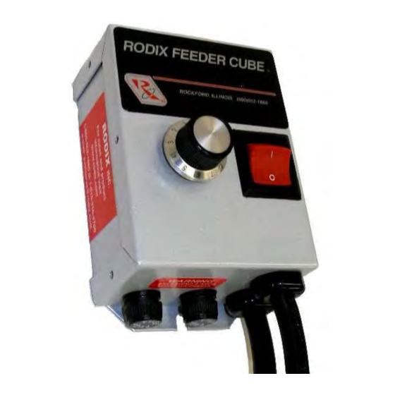
FEEDER CUBE
FEEDER CUBE
Plus Series
FC-70 SERIES
FC-90
OPEN FRAME
GENERAL PURPOSE
Plus
Model - FC-75
P/N 121-000-1110
Circuit Board P/N 24-214
Input: 120 VAC, 50/60 HZ.
(Operating range 100-130 VAC)
Single Unit Fuse Size: 5 AMPS
Output: 0-120 VAC
© 2015 RODIX
.
INC
ADJUSTMENTS
Warning: To avoid shock, remove power
before making any changes to the circuit
board settings or connections. The
control is not isolated from the power
line.
1. SELECT THE PULSE SETTING
Match the control's pulse mode to the feeder's tuning:
A. For 60 pulse output - Set DIP switch (S1, position
1) to 60 on the circuit card.
B. For 120 pulse output - Set DIP switch (S1,
position 1) to 120 on the circuit card.
C. For 60 Reverse pulse setting see the "Feature
Programming Chart". The "60 Pulse Reverse"
feature is useful for reducing mechanical vibration
interaction between different feeder components
mounted on the same machine table. To
determine if there is a feeder interaction, remove
the power from one feeder. If a feeder interaction
exists, the feed rate on the other feeder will either
speed up or slow down.
D. For
40
Programming Chart". The 40 Pulse rate can be
useful in a minority of applications for feeding
heavy parts. The power output is not as high as
60 pulse mode.
converted to a lower pulse mode will require
fewer springs.
The output power is controlled by the AMPLITUDE
POT. It is a logarithmic-tapered power out curve
(non-linear) that spreads the power broadly across the
AMPLITUDE POT. The logarithmic taper power curve
helps to give maximum "Fine Control" over the output
speed of the vibratory feeder.
3. SETTING THE SOFT-START
The start-up rate of the control's output can be set to
ramp up to the desired output level instead of starting
abruptly. The Soft-start keeps parts from falling off
the tooling, reduces spring shock, and hammering
AND SET UP
pulse
output
see
the
"Feature
A vibratory feeder that is
2. AMPLITUDE POT
when the control turns ON. Set position 2 of S1
DIP switch to the ON position to enable the two
second SOFT Start function. Set position 2 of S1
DIP switch to the OFF position to disable the
SOFT Start function.
4. REMOTE OFF/ON CONTROL
A Run Jumper has been installed at the factory as
shown on the enclosed wiring diagram.
Remote OFF/ON operation of the FC-70 Series
Feeder Cube
control can be configured to operate
®
in one of the following ways.
A. A low current switch such as a paddle switch
can replace the factory-installed Run Jumper
"J1." The "Run Contact" connects to terminals
TB2-3 and 4. The contact must be isolated
and be able to switch 24VDC and 2mA. The
control will run when the contact is closed.
Refer to Section A of the OFF/ON CONTROL
GUIDE.
B. Low Voltage DC can be used to turn the
control ON and OFF. Remove jumper "J1"
from TB2 terminals 3 and 4. Then connect the
positive signal (+12 to 24VDC @ 5mA) to TB2
terminal 2 and the negative to terminal 1 of
TB2. The control will now turn ON when the
DC signal is present at terminals 1 and 2 of
TB2. This input is optically isolated. Refer to
Section B of the OFF/ON CONTROL GUIDE.
There is a "RUN" status LED that lights up when
either the low current switch is closed or when an
external low voltage DC signal is applied. The
control's output will be ON whenever the "RUN"
LED is lit and the AMPLITUDE POT is turned up.
5. LINE VOLTAGE COMPENSATION
Fluctuations in the line voltage can cause a feeder
bowl to vary its feed rate.
The line voltage
compensation feature adjusts the control's output
to help compensate for fluctuations in the supply
voltage. If it becomes necessary to disable this
feature, remove resistor "R20" from the circuit
board. R20 is located near the Triac labeled Q1.
With the input power disconnected, a knife can be
used to cut down through "R20".
FC-75 24-214.doc 12/23/2015 Page 1
Advertisement
Table of Contents

Related Manuals for Rodix FEEDER CUBE FC-70 Series


Summary of Contents for Rodix FEEDER CUBE FC-70 Series
- Page 1 With the input power disconnected, a knife can be Output: 0-120 VAC abruptly. The Soft-start keeps parts from falling off used to cut down through “R20”. © 2015 RODIX the tooling, reduces spring shock, and hammering FC-75 24-214.doc 12/23/2015 Page 1...
- Page 2 Rodix Inc., ATTN: Repair Department 6. FEATURE PROGRAMMING CHART If under warranty, Rodix will repair or replace your control at “X” means the setting could be in either position no charge; If out of warranty, we will repair it and you will be because the position doesn’t matter.
- Page 3 OFF/ON CONTROL GUIDE RODIX INC. See section 4 of the Application Note for more LOW VOLTAGE INPUT SWITCHING FEEDER CUBE details on the REMOTE OFF/ON CONTROL guide. (DC Voltage from PLC or FC-90 Plus) FC-70 Series LOW CURRENT SWITCH...
- Page 4 Rodix controls have been designed with a AUX output. The shield “drain” wire high degree of immunity to electrical RECTIFIER should be tied to the chassis in the Rodix noise; however, depending on the control RELAY DIODE control. The drain wire should be kept...
Need help?
Do you have a question about the FEEDER CUBE FC-70 Series and is the answer not in the manual?
Questions and answers