Advertisement
Quick Links
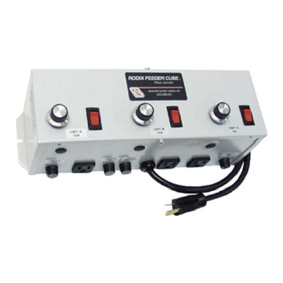
FEEDER CUBE ®
Plus
FC-112
GENERAL PURPOSE MODEL
IMPORTANT: APPLICATION NOTE
Input: 120 VAC, 50/60 HZ.
(Operating range 90-130 VAC)
Triple Unit Fuse Sizes:
Main 15 Amps Maximum
Unit A 10A, Unit B 15A, Unit C 5A
Output: 0-120 VAC
100% Duty Cycle 0.6-12A, 80% for 13-15A
Circuit Boards P/N 24-490 & 24-210
Unit A Information: This unit is based on the FC-90
this unit, refer to the enclosed Adjustments and Set Up pages. Unit A is interlocked (subordinate) to the operation of Unit
B so that Unit A operates only when Unit B is feeding parts.
Unit B Information: This unit is based on the FC-90
output can be controlled with an optional part sensor. For more information on this unit, refer to the enclosed Adjustments
and Set Up pages.
Unit C Information: This unit is based on the FC-40
to the enclosed Adjustments and Set Up pages. The Unit C operation is independent of the other units.
© 2000, 2018 RODIX
RODIX INCORPORATED
TOLL FREE (800) 562-1868, FAX (815) 316-4701
E-mail custserve@rodix.com
rodix.com
, P/N 121-000-8771
Plus
Plus
Plus
.
INC
Series Part Sensing Feeder Cube®. For more information on
Series Part Sensing Feeder Cube®. The On/Off operation of the
Series Feeder Cube®. For more information on this unit, refer
File No. E183233
FC-112.docx 2/19/2018
Page 1
Advertisement

Related Manuals for Rodix FEEDER CUBE FC-112 Plus


Summary of Contents for Rodix FEEDER CUBE FC-112 Plus
- Page 1 Unit C Information: This unit is based on the FC-40 Series Feeder Cube®. For more information on this unit, refer to the enclosed Adjustments and Set Up pages. The Unit C operation is independent of the other units. © 2000, 2018 RODIX FC-112.docx 2/19/2018 Page 1...
- Page 2 RUN JUMPER INPUT FEEDER BOWL/HOPPER LOW VOLTAGE INPUT RODIX INC. INTERLOCK SWITCHING P/N 24-490/24-491 FC-90 PLUS SERIES TB2, OUTPUT FEEDER CUBE (DC Voltage from PLC) LOW CURRENT SWITCH FC-90 Plus Series 5-30 VDC INPUT VOLTAGE OFF/ON CONTROL WIRING DIAGRAM ...
-
Page 3: Adjustments & Set Up
R3. R3 is located on the circuit maintain a constant part feed rate. linear pot taper for the Main Control Dial, see the “S1 board near TB2-8. Programming Chart.” © 2000, 2018 RODIX FC-90 Plus Set Up J.docx 2/21/2018 Page 3... - Page 4 B. CHOOSE A LOCATION for mounting the sensor Plus A. 4-20mA signal from a PLC can be used to remotely can be connected to a Rodix FC-40 Series on the feeder that is smooth and that will allow the Plus vary the output of the control instead of the Main (TB2-11 &...
-
Page 5: Warranty
OUT of warranty service, please ship it prepaid to: Rodix Inc., ATTN: Repair Department packaging. Remove the liner from the adhesive Included features: Constant On, High/Low Track level If under warranty, Rodix will repair or replace your control backing. Avoid touching the tape. Align the control, 60 pulse polarity reversal, low pulse rate, at no charge;... - Page 6 "Parts Sensing Feeder Bowl Control" such as an available for use on applications requiring a three Plus FC-90 wire DC sensor, an interlock output, or a Constant Feed Rate (vibration feedback) sensor. FC-40 Plus Set Up.doc 2/21/2018 Page 6 © 2000, 2017 RODIX...
- Page 7 ON and OFF. Move jumper "J1" from terminal If under warranty, Rodix will repair or replace your control pots. See the S1 Switch Programming Chart. For 7, to terminal 5, (6 remains the same). Then at no charge;...
-
Page 8: Rodix Solution
Rodix controls have been designed with a AUX output. The shield “drain” wire high degree of immunity to electrical should be tied to the chassis in the Rodix RECTIFIER noise; however, depending on the control RELAY DIODE control. The drain wire should be kept...
Need help?
Do you have a question about the FEEDER CUBE FC-112 Plus and is the answer not in the manual?
Questions and answers