Table of Contents
Advertisement
Available languages
Available languages
Advertisement
Table of Contents

Related Manuals for Helios KWL EC 300 Pro R


Summary of Contents for Helios KWL EC 300 Pro R
- Page 3 ß...
- Page 6 ° ° ° °...
- Page 14 * HINWEIS: Das KWL EC 300 Pro besitzt kein Nachheizregister. Daher bleibt die Zulufttemperatur-Einstellung ohne Auswirkung...
- Page 16 ACHTUNG! Bei der Kamin-Funktion muss die Feuerstättenverordnung unbedingt beachtet werden! ACHTUNG! Um ein Einfrieren der Geräte zu verhindern, ist die Funktion "Nachheizregister elektrisch" zwingend vorgeschrieben!
- Page 18 ·...
- Page 22 HELIOS Ventilatoren GmbH + Co KG · Lupfenstraße 8 · 78056 VS-Schwenningen HELIOS Ventilateurs · Le Carré des Aviateurs · 157 av. Charles Floquet · 93155 Le Blanc Mesnil Cedex CH HELIOS Ventilatoren AG · Steinackerstraße 36 · 8902 Urdorf GB HELIOS Ventilation Systems Ltd.
- Page 23 INSTALLATION AND OPERATING INSTRUCTIONS Model: KWL EC 300 Pro R KWL EC 300 Pro L with control panel including clock timer adjustable for each time of the week Controlled ventilation system with heat recovery.
-
Page 24: Table Of Contents
TABLE OF CONTENTS Thank you that you have decided on Helios ventilation system with heat recovery. Read the information summarised in the operation and installation instruction before the Helios unit is put into operation. In addition, you will find information about the maintenance and care which serves the proper functioning and conservation of value of your Helios unit. -
Page 25: General Informations
GENERAL INFORMATIONS Important informations Operation: Important information about the ventilation system as well as settings at the controller are specified here. Important Maintenance: In the maintenance part important information about filter changes and necessary ß cleaning and maintenance activities are specified. The user usually accomplishes maintenance work. - Page 26 GENERAL INFORMATIONS When screwing through the side panel, the fans, controler, heating element and electrical wiring must not be damaged or restricted in function. Sound and vibration transfer must be considered on site when installing the unit. It is necessary to connect the condensation spigot of the unit to a pipe connected to the drainage system of the house with a U bend trap in to prevent oders returning from the drains (see condensation run-off).
-
Page 27: Main Parts And Optional Equipment
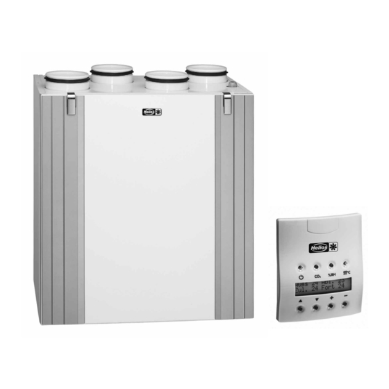
Extract air filter G4 Preheating radiator Plug Door switch-/service switch Connection box Control panel KWL-FB Ball Siphon Optional equipment (fig: KWL EC 300 Pro R) Carbon dioxide sensor KWL-KDF Humidity sensor KWL-FF 14 14 LON-transformer KWL-LB KWL EC 300 Pro R... -
Page 28: Functions
FUNCTIONS Models: KWL EC 300 Pro R / KWL EC 300 Pro L Case 1. Extract air flow 162 m KWL EC 300 Pro removes contaminated air and replaces it with fresh filtered and heated outdoor air. Efficient filtering of outdoor air (G4 + F7) prevents harmful particles from en... -
Page 29: Mounting Instructions
MOUNTING INSTRUCTIONS Montage – Location of KWL EC 300 Pro • The unit is mounted indoors, in a place where temperature does not fall below +5 °C. • If installed within not heated areas (e.g. cock loft) a sufficient isolation on all sides is to be mounted outside at the unit. -
Page 30: Mounting Of Control Panels And Sensors
MOUNTING OF CONTROL PANELS AND SENSORS Control panel mounting, detaching and wiring The control panel is wired (2 m cable lenght) directly from the KWL EC 300 Pro connection box. The control panel can also be wired serially with a CO sensor or another control panel. -
Page 31: Functions
FUNCTIONS Fan speed adjustment Heat recovery bypass Heat recovery is enabled when the defined conditions on page Manuel control 10 are fullfilled. In this case, the control unit directs the operation Fan speed of the ventilation unit is controlled in 8 steps at the of the damper motor on the basis of measuring results given by control panel. -
Page 32: Description Of Operation
DESCRIPTION OF OPERATION Ventilation control with CO sensor (option) • In CO sensor control, the ventilation unit adjusts fan speed so as to keep carbon dioxide content in the ventilation zone below the setpoint. When two or more sensors are used, fan speed is adjusted according to the highest measuring result. -
Page 33: Maintenance Reminder
DESCRIPTION OF OPERATION Maintenance reminder • The Maintenance reminder switches on the Maintenance reminder symbol ( ) in the main display of the control panel at defined intervals, the factory setting being 4 months. • The Maintenance reminder symbol is acknowledged at the control panel (see page 14, Section 1.3.10.). -
Page 34: Condensat Removal Via Ball Siphon
MOUNTING INSTRUCTIONS Condensate removal via ball siphon Humidity of the extract air condenses to water in the ventilation unit and flows out over a condensing water outlet in the bottom reservoir. For this the enclosed ball siphon (scope of supply) in the condensate opening of the bottom reservoir must be installed (see "Assembly of the ball siphon"). -
Page 35: Operation Instructions Of The Control Panel
OPERATION INSTRCTIONS OF THE CONTROL PANEL Control panel 1.1. Keyboard Start button Scrolling up With this button, you switch the Unit KWL EC 300 With this button, you can scroll the displays upward. Pro on and off. When the indicator is lit, the unit is Scrolling down With this button, you can scroll the displays Carbon dioxide adjustment... -
Page 36: Settings Menu
OPERATION INSTRUCTION OF THE CONTROL PANEL Settings menu The transition from the operating to setting menu occurs as specified in point 1.2.2. With the page keys (see point 1.1, illustration text 5 and 6) individual displays of the setting menu (point 1.3.1 –... - Page 37 OPERATION INSTRUCTION OF THE CONTROL PANEL 1.3.5. Change clock time In order to enter into the menu "change clock time", pressing + and - buttons Change clock time simultaneously. Press + and - Move cursor with arrow keys und change the values with + and - buttons. day hour Min To complete the changes quit over "exit".
- Page 38 OPERATION INSTRUCTION OF THE CONTROL PANEL 1.3.16. Setpoint of the basic humidity level The desired setpoint is selected with the + and - buttons, unless automatic search of the Basic %RH level basic humidity level is used. 1.3.17. Mode of operation of the fireplace/booster switch The mode of operation of the switch (either fireplace or booster switch) is selected with the Switch type + and - buttons.
-
Page 39: Factory Settings
FACTORY SETTINGS 1.4. Factory Settings Unit KWL EC 300 Pro has the following factory settings: Basic fan speed Maximum fan speed )-adjustment = 900 ppm CO Basic humidity level = value chosen either automatically or manually Adjustment intervall = 10 min. Freezing protection (cell) = 3 °C Freezing protection hysteresis... -
Page 40: Performance
PERFORMANCE · Parts list KWL EC 300 Pro Measuring points after the spigots. The performance curves indicate the available total pressure for the pressure loss in the duct system. Adjustment Total input power range (both fans) 20 W 36 W 50 W 72 W 92 W... -
Page 41: Wiring
WIRING... -
Page 42: Maintenance
MAINTENANCE ATTENTION: All work only in dead state! Before maintenance an isolator is required for with a minimum of 3 mm contact opening of each pole. Electrical connection should only be carried out by a qualified person. Filter and heat recovery cell •... -
Page 43: Other Cleaning
Damage arising from such usage is not covered by the guarantee. Warranty – Exclusion of liability If the preceding instructions are not observed all warranty claims are void. The Helios warranty is limited to the material and workmanship of the product. -
Page 44: Operation Failures / Alarms
HELIOS Ventilatoren GmbH + Co KG · Lupfenstraße 8 · 78056 VS-Schwenningen HELIOS Ventilateurs · Le Carré des Aviateurs · 157 av. Charles Floquet · 93155 Le Blanc Mesnil Cedex CH HELIOS Ventilatoren AG · Steinackerstraße 36 · 8902 Urdorf GB HELIOS Ventilation Systems Ltd. - Page 45 NOTICE DE MONTAGE ET D’UTILISATION Modèles: KWL EC 300 Pro R KWL EC 300 Pro L avec commande à distance et horloge hebdomadaire inclus...
- Page 46 SOMMAIRE INTRODUCTION NOTICE DE MONTAGE ET D'UTILISATION INSTALLATION DE LA COMMANDE A DISTANCE ET DES SONDES DESCRIPTION DU FONCTIONNEMENT MODE D'EMPLOI MODE D'EMPLOI DE LA COMMANDE A DISTANCE CHARACTERISTIQUES TECHNIQUES RACCORDEMENTS ELECTRIQUES EXTERNES ENTRETIEN DEFAUTS DE FONCTIONNEMENT...
- Page 47 REMARQUES GENERALES Remarques importantes concernant cette notice Mode d'emploi: Entretien: Remarques importantes! ß Montage: Documentation technique: Consignes de sécurité Réception des colis KWL EC 300 Pro avec la commande à distance. Stockage Domaine d’utilisation Fonctionnement Caracteristiques Techniques...
- Page 48 REMARQUES GENERALES Notices explicatives Montage – Disposition Foyers ouverts Recommandations générales Recommandations particulières Raccordement électrique Attention: Le branchement électrique doit être effectué par un électricien qualifié! Réseaux et débits d’air Important:...
- Page 49 Boîtier de connexion Cde à distance KWL-FB Siphon à boule Accessoires Sonde CO 2 KWL-KDF Sonde d'humidite KWL-FF Module Bus LON KWL-LB KWL EC 300 Pro R AIR EXTRAIT AIR NEUF AIR REPRIS AIR EXTÈRIEUR Alimentation d électronique Classe de protection Ventilateurs Récupération de la chaleur...
- Page 50 PRINCIPE DE FUNCTIONNEMENT Modèles: KWL EC 300 Pro R / KWL EC 300 Pro L Exemple 1 162 m Débit extraction 162 m Débit soufflage ° Température air repris ° Température air extérieur Hygrométrie air repris 35 % 90 % Hygrométrie extérieur...
- Page 51 NOTICE DE MONTAGE ET D'UTILISATION Montage du groupe KWL EC 300 Pro · · · · · · Raccordements des conduits · Raccordement électrique KWL EC 300 Pro Les raccordements électriques en 230 VAC 50Kz doivent être effectués par une personne autorisée! Prévoir un dispositif de coupure du courant avec un écartement des contacts de min.
- Page 52 INSTALLATION DE LA COMMANDE A DISTANCE ET DES SONDES Commande à distance: installation, équipement et câblage Montage apparent Câblage ATTENTION: Branchement de plusieurs commandes à distances Exemple: branchement de3 commandes à distance Une défaillance du bus intervient si les commandes à distance ont la même adresse. Dans ce cas, couper la Adresse CAD seconde commande à...
- Page 53 DESCRIPTION DU FONCTIONNEMENT Régulation de la vitesse des ventilateurs Température de l'air neuf Commande manuelle Automatique par horloge externe Fonction de bypass Régulation par sondes CO et hygrométriques Protection antigel de l'échangeur de chaleur Commande par signal de tension ou de courant externes Protection contre les surchauffes Valeurs des signaux de tension et courant Etages...
- Page 54 MODE D'EMPLOI Régulation du renouvellement d'air par la sonde CO 2 (option) · · · · Sonde CO L'activation de la fonction CO , active également la fonction limitation haute du débit d'air. Régulation du renouvellement d'air par la sonde hygrométrique (option) Sonde hygrométrique ·...
- Page 55 MODE D'EMPLOI Protection contre le givrage de l'échangeur de chaleur Si le dégivrage doit être réalisé avec la batterie électrique, il faut régler la température de préchauffage à +5 °C (réglage usine -3 °C) Témoin d'entretien Ventilation forcée ou allumage cheminée Marche forcée ( ).
- Page 56 MONTAGE ET UTILISATION Evacuation des condensats par siphon à boule IMPORTANT: - Le réseau d'évacuation en aval du siphon doit être en pente pour garantir l'écoulement. Siphon à boule - L'orifice d'évacuation des condensats est situé au milieu de l'appareil. Vérifier que la centrale est bien 100 % à...
- Page 57 MODE D'EMPLOI DE LA COMMANDE A DISTANCE Commande à distance 1.1. Touches Start Défilement vers le haut Défilement vers le bas Régulation CO Touche plus Régulation de l'humidité Touche moins Mode été/ hiver Contact cheminée ou marche forcée Coupure de courant Après une coupure de courant, l'appareil se met en route au débit minimum.
- Page 58 MODE D'EMPLOI DE LA COMMANDE A DISTANCE Mode programmation Vent.permanente Menu principal Appuyer + et - Effacer prog heb Appuyer + et - Modifier l' horaire Appuyer + et - d hr sp Tmp 1 12 5 20 Exit Exemple: Lundi Exit "Exit"...
- Page 59 MODE D'EMPLOI DE LA COMMANDE A DISTANCE Modifier l' horaire Appuyer + et - day hour Min 30 Exit hour Nota: l'horaire reste en mémoire même après une coupure de courant! Exit Ventilation max. toujours active Kieli / Language Francais Reinitialisation d'usine voir mode d'emploi...
- Page 60 MODE D'EMPLOI DE LA COMMANDE A DISTANCE Limitation %HR Contact externe BP cheminee Attention! En mode allumage cheminée, il faut tenir compte des législations régionales ou nationales. Voir page 4. Non utilisé sur ce produit Cde en cascade marche Controle HR automatique Non utilisé...
- Page 61 MODE D'EMPLOI DE LA COMMANDE A DISTANCE 1.4. Réglages d'usine Le groupe double flux KWL EC 300 Pro est livré d'usine avec les réglages suivants: Informations sur le reset du software: Si la régulation est réinitialisée avec les réglages d'usine, voir point 1.3.8. page 12, les valeurs ci-dessus sont reprises à...
- Page 62 CARACTERISTIQUES TECHNIQUES COURBE DE VENTILATION Description KWL EC 300 Pro Valeurs Données Description Livraison ((réglages usine (..) )) 20 W 36 W 50 W 72 W 92 W 130 W 160 W 194 W...
- Page 63 RACCORDEMENTS ELECTRIQUES EXTERNES...
- Page 64 ENTRETIEN Filtres et échangeur de chaleur Attention: Pour toute intervention sur l'appareil il est nécessaire de couper l'alimentation électrique. Pendant les travaux de maintenance, le groupe doit être isolé du réseau électrique par un commutateur multipolaire ayant un écartement des contacts d'au moins 3 mm. Filtres et échangeur de chaleur Filtre grossier G4 Filtre fin F7...
- Page 65 ENTRETIEN Généralités Bouches de soufflage et d'extraction Prise d'air extérieur Accessoires, appareils de commande Demande de garantie - Réserves du constructeur Règlementations + Normes...
- Page 66 HELIOS Ventilatoren GmbH + Co KG · Lupfenstraße 8 · 78056 VS-Schwenningen HELIOS Ventilateurs · Le Carré des Aviateurs · 157 av. Charles Floquet · 93155 Le Blanc Mesnil Cedex CH HELIOS Ventilatoren AG · Steinackerstraße 36 · 8902 Urdorf GB HELIOS Ventilation Systems Ltd.
Need help?
Do you have a question about the KWL EC 300 Pro R and is the answer not in the manual?
Questions and answers