
Subscribe to Our Youtube Channel
Related Manuals for Xylem wtw Multi 3510 IDS


Summary of Contents for Xylem wtw Multi 3510 IDS
- Page 1 OPERATING MANUAL ba77160e07 10/2021 Multi 3510 IDS DIGITAL METER FOR DIGITAL IDS SENSORS (pH/ORP/D.O./COND)
- Page 2 Multi 3510 IDS Copyright © 2021 Xylem Analytics Germany GmbH Printed in Germany. ba77160e07 10/2021...
-
Page 3: Table Of Contents
Multi 3510 IDS Contents Contents Overview ......... . 7 Multi 3510 IDS meter . - Page 4 Contents Multi 3510 IDS pH value......... . 26 Measuring .
- Page 5 Multi 3510 IDS Contents ® Turbidity measurement (VisoTurb 900-P) ... . . 60 Measuring ........60 9.1.1 Measuring the turbidity .
- Page 6 Contents Multi 3510 IDS 13 Maintenance, cleaning, disposal..... . 89 13.1 Maintenance ........89 13.1.1 General maintenance activities .
-
Page 7: Overview
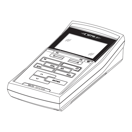
Multi 3510 IDS Overview Overview Multi 3510 IDS meter The Multi 3510 IDS meter enables you to perform measurements (pH, U, ISE, conductivity, D.O. turbidity) quickly and reliably. The Multi 3510 IDS provides the maximum degree of operating comfort, reli- ability and measuring certainty for all applications. -
Page 8: Ids Sensors
Overview Multi 3510 IDS Information on available IDS sensors and IDS adapters is given on the Internet . You can also operate non-IDS sensors with the aid of an IDS adapter on the Multi 3510 IDS. The advantages of the sensor recognition, however, are not available in this case. -
Page 9: Ids Adapter For Analog Sensors
Multi 3510 IDS Overview 1.2.3 IDS adapter for analog sensors With the aid of an IDS adapter, you can also operate analog sensors on the Multi 3510 IDS. The combination of the IDS adapter and analog sensor behaves like an IDS sensor. The measuring electronics with the stored adapter data are in the adapter head. - Page 10 Overview Multi 3510 IDS ba77160e07 10/2021...
-
Page 11: Safety
Multi 3510 IDS Safety Safety Safety information 2.1.1 Safety information in the operating manual This operating manual provides important information on the safe operation of the meter. Read this operating manual thoroughly and make yourself familiar with the meter before putting it into operation or working with it. The operating manual must be kept in the vicinity of the meter so you can always find the infor- mation you need. -
Page 12: Safe Operation
Safety Multi 3510 IDS Safe operation 2.2.1 Authorized use The authorized use of the meter consists exclusively of the measurement of the pH, ORP, conductivity and dissolved oxygen in a laboratory environment. Only the operation and running of the meter according to the instructions and technical specifications given in this operating manual is authorized (see section 15 T , page 97). -
Page 13: Commissioning
Multi 3510 IDS Commissioning Commissioning Scope of delivery Meter Multi 3510 IDS 4 batteries 1.5 V Mignon type AA Short instructions CD-ROM with – USB drivers – comprehensive operating manual (4 languages) – software MultiLab User –... -
Page 14: Inserting The Batteries
Commissioning Multi 3510 IDS 3.3.1 Inserting the batteries You can operate the meter either with normal batteries or with rechargeable batteries (Ni-MH). In order to charge the batteries, an external charging device is required. 1 Screws 2 Battery compartment Unscrew the two screws (1) on the underside of the meter. Open the battery compartment (2) on the underside of the meter. -
Page 15: Operation
Multi 3510 IDS Operation Operation General operating principles 4.1.1 Keypad In this operating manual, keys are indicated by brackets <..>. The key symbol (e.g. <ENTER>) generally indicates a short keystroke (press and release) in this operating manual. A long keystroke (press and hold for approx. -
Page 16: Display
Operation Multi 3510 IDS 4.1.2 Display Example (pH): AutoCal TEC HOLD AR 03.04.2013 USB output 08:00 1 Status information (sensor) 2 Measured value 3 Measured parameter 4 Continuous measurement control (CMC function) 5 Sensor symbol (calibration evaluation, calibration interval) 6 Measured temperature (with unit) 7 Status information (meter) 8 Softkeys and date + time 4.1.3 Status information (meter) -
Page 17: Instrument Connectors
Multi 3510 IDS Operation 4.1.4 Instrument connectors 1 IDS sensors: (pH, ORP, conductivity, D.O.) 2 USB B (device) interface 3 Service interface CAUTION Only connect sensors to the meter that cannot return any volt- ages or currents that are not allowed (> SELV and > current circuit with current limiting). -
Page 18: Switching On The Meter
Operation Multi 3510 IDS 7.007 25.0 °C SenTix 940 03.04.2013 More B09250001 08:00 Display further sensor data (settings) with <F1>/[More]. SenTix 940 B092500013 pH resolution 0.001 mV resolution Buffer Calibration interval Unit for slope mV/pH QSC: Software-Version V 1.00 03.04.2013 Back 08:00 Switching on the meter... -
Page 19: Switching Off The Meter
Multi 3510 IDS Operation Switching off the meter Switch the meter off with <On/Off>. Login with a user name After activation of the user administration by the administrator (software MultiLab User, on the enclosed CD-ROM), measurements are only possible after login with a user name. The user name is documented with the measured values and in records. -
Page 20: Navigation
Operation Multi 3510 IDS The user specifies the password when he or she first logs in with a user name. A valid password consists of 4 digits. The user can change the password with the next login. Change the digit of the highlighted position with < >< >. Go to the next digit of the password with <F2>/[]. -
Page 21: Measured Value Display
Multi 3510 IDS Operation Operating Description mode Transmit- The meter transmits measuring data and calibration ting data records to a USB-B interface automatically or manually. Setting The system menu or a sensor menu with submenus, set- tings and functions is displayed 4.5.2 Measured value display In the measured value display, you can ... - Page 22 Operation Multi 3510 IDS General Language: English Audio signal: Illumination: Contrast: Shutoff time: Temperature unit: °C Stability control 03.04.2013 Back 08:00 Functions Functions are designated by the name of the function. They are immediately carried out by confirming with <ENTER>. Example: Display the Calibration record function.
-
Page 23: Example 1 On Navigation: Setting The Language
Multi 3510 IDS Operation 4.5.4 Example 1 on navigation: Setting the language Press the <On/Off> key. The measured value display appears. The instrument is in the measuring mode. 7.007 25.0 °C 01.02.2014 USB output 08:00 Using <ENTER_ >, open the Storage & config menu. The instrument is in the setting mode. -
Page 24: Example 2 On Navigation: Setting The Date And Time
Operation Multi 3510 IDS Select the General submenu with < >< >. The current selection is displayed with a frame. Open the General submenu with <ENTER>. General Language: English Audio signal: Illumination: Contrast: 50 % Shutoff time: Temperature unit: °C Stability control 03.04.2013 Back... - Page 25 Multi 3510 IDS Operation Therefore, check the time at regular intervals. After a fall of the supply voltage (empty batteries), the date and time are reset. Setting the date, The date format can be switched from the display of day, month, year time and date format (dd.mm.yy) to the display of month, day, year (mm/dd/yy or mm.dd.yy).
-
Page 26: Ph Value
pH value Multi 3510 IDS pH value Measuring 5.1.1 Measuring the pH value NOTE When connecting a grounded PC/printer, measurements cannot be performed in grounded media as the values would be incorrect. The USB interface is not galvanically isolated. Connect the IDS pH sensor to the meter. The pH measuring window is displayed. -
Page 27: Measuring The Temperature
Multi 3510 IDS pH value You can terminate the Stability control function and the HOLD func- tion with <AR> or <M> at any time. Using <ENTER>, activate the Stability control function manually. The [AR] status indicator appears while the measured value is assessed as not stable. -
Page 28: Ph Calibration
pH value Multi 3510 IDS mode: Temperature Resolution of the Temp. measurement sensor temp. display 0.1 °C Automatic with temperature sensor 1 °C Manual pH calibration 5.2.1 Why calibrate? pH electrodes age. This changes the zero point (asymmetry) and slope of the pH electrode. - Page 29 Multi 3510 IDS pH value Buffer -180.0 24.8 °C AutoCal TEC 01.07.2011 08:00 Thoroughly rinse the sensor with deionized water. Immerse the sensor in the first buffer solution. For measurements without temperature sensor (e.g. when using an IDS adapter Measure the temperature of the buffer manually and enter it with <...
- Page 30 pH value Multi 3510 IDS When measuring without temperature sensor: Measure the temperature of the buffer manually and enter it with < >< >. Start the measurement with <ENTER>. The measured value is checked for stability (stability control). The [AR] status indicator is displayed. The measured parameter flashes.
-
Page 31: Carrying Out Manual Calibration (Concal)
Multi 3510 IDS pH value Wait for the measurement with stability control to be completed or ter- minate the stability control and take over the calibration value with <ENTER>. The calibration display for the next buffer appears (voltage display). If necessary, use <M> to finish the calibration. The calibration record is displayed. - Page 32 pH value Multi 3510 IDS Thoroughly rinse the sensor with deionized water. Immerse the pH sensor in buffer solution 1. For measurements without temperature sensor (e.g. when using an IDS adapter Measure the temperature of the buffer manually and enter it with <...
- Page 33 Multi 3510 IDS pH value For single-point calibration, the instrument uses the Nernst slope (-59.2 mV/pH at 25 °C) and determines the zero point of the IDS pH sensor. Continuing with two- Thoroughly rinse the sensor with deionized water. point calibration Immerse the pH sensor in buffer solution 2.
-
Page 34: Calibration Points
pH value Multi 3510 IDS Start the measurement with <ENTER>. The measured value is checked for stability (stability control). The [AR] status indicator is displayed. The measured parameter flashes. Wait for the measurement with stability control to be completed or termi- nate the stability control and take over the calibration value with <ENTER>. -
Page 35: Calibration Data
Multi 3510 IDS pH value Calibration Determined values Displayed calibration data 3-point to 5- Zero point = Asy point Slp. Slope = Slp. The calibration line is calculated by linear regression. You can display the slope in the units, mV/pH or % (see section 10.1.1 S , page 67). - Page 36 pH value Multi 3510 IDS Calibration After calibrating, the meter automatically evaluates the calibration. The zero evaluation point and slope are evaluated separately. The worse evaluation of both is taken into account. The evaluation appears on the display and in the calibration record.
-
Page 37: Continuous Measurement Control (Cmc Function)
Multi 3510 IDS pH value 5.2.7 Continuous measurement control (CMC function) The Continuous Measurement Control (CMC function) facilitates to evaluate the current measured value instantly and definitely. After each successful calibration the scale of the pH measuring range is dis- played in the measured value display. -
Page 38: Qsc Function (Sensor Quality Control)
pH value Multi 3510 IDS 5.2.8 QSC function (sensor quality control) General information The QSC function (Quality Sensor Control) is a new sensor evaluation for on the QSC function digital IDS sensors. It evaluates the condition of an IDS pH sensor individually and with a very fine grading. - Page 39 Multi 3510 IDS pH value Carry out the normal calibrations for your special measuring range with your usual standard solutions as previously done. As soon as the QSC function was enabled for an IDS sensor, it is not possible to return to the sensor evaluation with the sensor symbol for this sensor.
- Page 40 pH value Multi 3510 IDS sor evaluation. 7.007 25.0 °C 01.02.2014 USB output 08:00 1 QSC scale The double arrow on the QSC scale indicates the current sensor evaluation Carrying out a QSC A QSC control calibration can, e.g. be useful if the sensor evaluation noticeably control calibration changed (after some normal calibrations).
-
Page 41: Orp
Multi 3510 IDS Measuring 6.1.1 Measuring the ORP NOTE When connecting a grounded PC/printer, measurements cannot be performed in grounded media as the values would be incorrect. The USB interface is not galvanically isolated. IDS ORP sensors are not calibrated. However, you can check IDS ORP sensors using a test solution. - Page 42 Multi 3510 IDS You can terminate the Stability control function and the HOLD func- tion with <AR> or <M> at any time. Using <ENTER>, activate the Stability control function manually. The [AR] status indicator appears while the measured value is assessed as not stable.
-
Page 43: Measuring The Temperature
Multi 3510 IDS 6.1.2 Measuring the temperature For reproducible ORP measurements, it is essential to measure the tempera- ture of the test sample. When operating a sensor without integrated temperature sensor, you first have to measure and enter the temperature of the sample. The measuring instrument recognizes whether a suitable sensor is connected and automatically switches on the temperature measurement. -
Page 44: Dissolved Oxygen
Dissolved oxygen Multi 3510 IDS Dissolved oxygen Measuring 7.1.1 Measuring D.O. Connect the IDS D.O. sensor to the meter. The D.O. measuring screen is displayed. If necessary, select the measured parameter with <M>. Check or calibrate the meter with the sensor. ®... - Page 45 Multi 3510 IDS Dissolved oxygen Air pressure The integrated air pressure sensor of the Multi 3510 IDS measures the current correction air pressure. The air pressure is automatically used for air pressure correction during calibrating and for the display of the oxygen saturation [%] parameter. current air pressurewhen an IDS D.O.
-
Page 46: Measuring The Temperature
Dissolved oxygen Multi 3510 IDS Criteria for a stable The Stability control function checks whether the measured values are stable measured value within the monitored time interval. Measured parame- Time interval Stability in the time interval D.O. concentration 20 seconds Δ... -
Page 47: Fdo Check Procedure
Multi 3510 IDS Dissolved oxygen ® Check procedure 7.2.1 Why should you check the sensor? ® With the FDO Check procedure, you can find out in a simple manner ® whether the FDO 925 D.O. sensor should be cleaned or calibrated. 7.2.2 When should you check the sensor? Checking can be useful in the following cases: ... -
Page 48: Evaluation
Dissolved oxygen Multi 3510 IDS 99.8 25.0 °C FDO Check [t90= 30 s] 01.02.2014 08:00 Start the measurement with <ENTER>. The measured value is checked for stability (stability control). The [AR] status indicator is displayed. The measured parameter flashes. Wait for the end of the AutoRead measurement ([HOLD][AR]) status indicator or take over the measured value with <ENTER>. -
Page 49: Calibration
Multi 3510 IDS Dissolved oxygen Calibration 7.3.1 Why calibrate? D.O. sensors age. This changes the slope of the D.O. sensor. Calibration deter- mines the current slope of the sensor and stores this value in the instrument. ® The FDO 925 D.O. sensor ages so little it does not have to be reg- ularly calibrated. -
Page 50: Calibration By Means Of A Comparison Meas. (Fdo Comp)
Dissolved oxygen Multi 3510 IDS Start the calibration with <CAL>. The last calibration data (relative slope) is displayed. 1.00 25.0 °C FDO Cal 01.02.2014 08:00 Start the measurement with <ENTER>. The measured value is checked for stability (stability control). The [AR] status indicator is displayed. The measured parameter flashes. Wait for the end of the AutoRead measurement ([HOLD][AR]) status indi- cator. -
Page 51: Calibration Data
Multi 3510 IDS Dissolved oxygen 7.92 mg/l 25.1 °C FDO Comp 03.04.2013 08:00 Start the measurement with <ENTER>. The measured value is checked for stability (stability control). The [AR] status indicator is displayed. The measured parameter flashes. Wait for the end of the AutoRead measurement or accept the calibration value with <ENTER>. - Page 52 Dissolved oxygen Multi 3510 IDS The calibration records of the last 10 calibrations are to be found in the menu, Calibration/Calibration data storage / Display. To open the Calibration menu, press the <ENTER> key in the measured value display. Menu item Setting/ Description function...
- Page 53 Multi 3510 IDS Dissolved oxygen Calibration record CALIBRATION Ox (USB output) 03.04.2013 07:43:33 FDO 925 Ser. no. 10146858 SC-FDO 925 10158765 Relative slope 0.98 Sensor ba77160e07 10/2021...
-
Page 54: Conductivity
Conductivity Multi 3510 IDS Conductivity Measuring 8.1.1 Measuring the conductivity NOTE When connecting a grounded PC/printer, measurements cannot be performed in grounded media as the values would be incorrect. The USB interface is not galvanically isolated. Connect the conductivity sensor to the meter. The conductivity measuring window is displayed. -
Page 55: Measuring The Temperature
Multi 3510 IDS Conductivity ting for automatic Stability control (see section 10.6.3 A UTOMATIC TABILITY , page 77) in the System menu. CONTROL Freeze the measured value with <AR>. The [HOLD] status indicator is displayed. The HOLD function is active. You can terminate the Stability control function and the HOLD func- tion with <AR>... -
Page 56: Temperature Compensation
Conductivity Multi 3510 IDS temperature of the test sample. IDS sensors measure the temperature with a temperature sensor integrated in the IDS sensor. Temperature compensation The calculation of the temperature compensation is based on the preset refer- ence temperature, 20 °C or 25 °C. It appears on the display as Tr20 or Tr25. You can select one of the following temperature compensation methods: ... -
Page 57: Calibration
Multi 3510 IDS Conductivity Calibration 8.3.1 Why calibrate? Aging slightly changes the cell constant, e. g. due to coatings. As a result, an inexact measured value is displayed. The original characteristics of the cell can often be restored by cleaning the cell. Calibration determines the current value of the cell constant and stores this value in the meter. -
Page 58: Calibration Data
Conductivity Multi 3510 IDS Immerse the conductivity sensor in the control standard solution, 0.01 mol/l KCI. Start the measurement with <ENTER>. The measured value is checked for stability (stability control). The [AR] status indicator is displayed. The measured parameter flashes. Wait for the end of the measurement with stability control ([HOLD][AR]) status indicator or take over the calibrated value with <ENTER>. - Page 59 Multi 3510 IDS Conductivity Menu item Setting/ Description function Calibration / Outputs the calibration data storage to the interface Calibration data storage / Output to RS232/USB Calibration After calibration, the meter automatically evaluates the current status of the cal- evaluation ibration.
- Page 60 ® Turbidity measurement (VisoTurb 900-P) Multi 3510 IDS ® Turbidity measurement (VisoTurb 900-P) Measuring 9.1.1 Measuring the turbidity The sensor connection and the USB-B (device) interface are gal- vanically insulated. This facilitates interference-free measurements also in the following cases: Measurement in grounded test samples ...
- Page 61 ® Multi 3510 IDS Turbidity measurement (VisoTurb 900-P) Immerse the sensor in the test sample at an angle and then position it in the measuring container. 7.92 01.02.2014 USB output 08:00 Selecting the You can switch between the following displays with <M>: displayed ...
- Page 62 ® Turbidity measurement (VisoTurb 900-P) Multi 3510 IDS Using <ENTER>, activate the Stability control function manually. The [AR] status indicator appears while the measured value is assessed as not stable. A progress bar is displayed and the display of the measured parameter flashes. The [HOLD][AR] status indicator appears as soon as a stable mea- sured value is recognized.
- Page 63 ® Multi 3510 IDS Turbidity measurement (VisoTurb 900-P) 9.2.3 Calibration standards Calibrate with 1 to 3 turbidity standard solutions. The standard solutions must be selected in the following order. Standard solution Range (FNU/NTU) 0.0 ... 1.0 5.0 ... 200.0 200.0 ... 4000.0 The turbidity expected in the measurement dictates the number and selection of the standards.
- Page 64 ® Turbidity measurement (VisoTurb 900-P) Multi 3510 IDS Start the calibration with <CAL>. The calibration display appears. Standard 000.0 FNU 01.07.2011 08:00 Thoroughly rinse the turbidity sensor with distilled water and dry it with a lint-free cloth. Immerse the turbidity sensor in the test sample at an angle. Position the turbidity sensor in the measuring vessel.
- Page 65 ® Multi 3510 IDS Turbidity measurement (VisoTurb 900-P) Wait for the end of the AutoRead measurement. The calibration display for the next standard solution appears. Standard 124.0 1010.0 FNU 01.07.2011 08:00 If necessary, terminate the calibration as a two-point calibration with <M>.
- Page 66 ® Turbidity measurement (VisoTurb 900-P) Multi 3510 IDS Menu item Setting/ Explanation function Calibration / Displays the calibration record. Calibration data storage / Display Further options: Scroll through the calibration records with < >< >. Output the displayed calibration record to the interface with <PRT>.
- Page 67 Multi 3510 IDS Settings Settings 10.1 pH measurement settings 10.1.1 Settings for pH measurements Settings The settings are made in the menu for calibration and measurement settings of the pH/ORP measurement. To open the settings, display the required mea- sured parameter in the measured value display and press the <ENTER> key. After completing the settings, switch to the measured value display with <M>.
- Page 68 Settings Multi 3510 IDS Menu item Possible Description setting 0.001 Resolution of the pH display pH resolution 0.01 Resolution of the mV display mV resolution Resets all sensor settings to the delivery condition (see sec- Reset tion 10.7.1 R , page 78). ESETTING THE MEASUREMENT SETTINGS 10.1.2 Buffer sets for calibration You can use the buffer sets quoted in the table for an automatic calibration.
- Page 69 Multi 3510 IDS Settings Buffer set * pH values 1.090 25 °C DIN 19267 4.650 6.790 9.230 1.679 25 °C Mettler Toledo USA * 4.003 7.002 10.013 1.995 25 °C Mettler Toledo EU * 4.005 7.002 9.208 2.007 25 °C Fisher * 4.002 7.004...
- Page 70 Settings Multi 3510 IDS Buffer set * pH values Reagecon 20 * 2.000 20°C 4.000 7.000 10.000 13.000 Reagecon 25 * 2.000 25 °C 4.000 7.000 10.000 13.000 Riedel-de Haen * 2.000 20 °C 4.000 7.000 10.000 USABlueBook * 4.000 25 °C 7.000 10.000...
- Page 71 Multi 3510 IDS Settings You can change the interval (1 ... 999 days): Open the menu for measurement settings with <ENTER>. In the Calibration / Calibration interval menu, set the calibration interval with < >< >. Confirm the setting with <ENTER>. Quit the menu with <M>.
- Page 72 Settings Multi 3510 IDS Menu item Possible Description setting Calibration / Outputs the calibration data storage to the interface Calibration data storage / Output to RS232/USB Calibration /Cali- Calibration interval for the IDS D.O. 1 ... 180 ... sensor (in days). bration interval 999 d The meter reminds you to calibrate...
- Page 73 Multi 3510 IDS Settings 10.4 Cond measurement settings 10.4.1 Settings for IDS conductivity sensors Settings The settings are made in the menu for the measured parameter, conductivity. To open the settings, display the required measured parameter in the mea- sured value display and press the <ENTER> key. After completing the settings, switch to the measured value display with <M>.
- Page 74 Settings Multi 3510 IDS Menu item Possible Description setting Temp. comp. (TC) / Coefficient of the linear temperature 0.000 ... compensation. Linear coeff. 2.000 ... This menu item is only available when 3.000 %/K the linear temperature compensation is set. Temp.
- Page 75 Multi 3510 IDS Settings 10.5 Turb measurement settings 10.5.1 Settings for turbidity sensors The settings are made in the menu for the measured parameter, turbidity. To open the settings, display the required measured parameter in the measured value display and press the <ENTER> key. After completing the settings, switch to the measured value display with <M>.
- Page 76 Settings Multi 3510 IDS 10.6 Sensor-independent settings 10.6.1 System To open the Storage & config menu, press the <ENTER_ > key in the measured value display. After completing the settings, switch to the measured value dis- play with <M>. Default settings are printed in bold. Menu item Setting Description...
- Page 77 Multi 3510 IDS Settings Menu item Setting Description System /Reset Resets the system settings to the default values. For details, see section 10.7.2 R ESET , page 80 TING THE SYSTEM SETTINGS 10.6.2 Data storage This menu contains all functions to display, edit and erase stored measured values.
- Page 78 Settings Multi 3510 IDS You can also generally switch on the display illumination (see section 10.6.1 , page 76). YSTEM 10.7 Reset You can reset (initialize) all sensor settings and sensor-independent settings separately from each other. 10.7.1 Resetting the measurement settings The calibration data are reset to the default settings together with the measuring parameters.
- Page 79 Multi 3510 IDS Settings The following settings for ORP measurements are reset to the default settings with the Reset function: Setting Default settings mV resolution 25 °C Man. temperature The sensor settings are reset under the Reset menu item in the menu for cali- bration and measurement settings.
- Page 80 Settings Multi 3510 IDS The sensor settings are reset under the Reset menu item in the menu for cali- bration and measurement settings. To open the settings, display the required measured parameter in the measured value display and press the <ENTER> key.
- Page 81 Multi 3510 IDS Data storage Data storage You can save measured values (datasets) to the data storage: Manual data storage (see section 11.1 M , page 81) ANUAL DATA STORAGE Automatic data storage at intervals (see section 11.2 A UTOMATIC DATA STOR , page 82) AGE AT INTERVALS...
- Page 82 Data storage Multi 3510 IDS 11.2 Automatic data storage at intervals The data storage interval (Interval) determines the time interval between auto- matic data storage processes. Each data storage process transmits the current dataset to the USB interface. Configuring the Press the <STO_ >...
- Page 83 Multi 3510 IDS Data storage Starting the To start the automatic data storage function, select continue with < >< > and automatic data confirm with <ENTER>. The meter switches to the measured value display. storage function 7.007 25.0 °C 0d03h00min 03.04.2013 08:00 1 Remaining storage duration...
- Page 84 Data storage Multi 3510 IDS 11.3 Measured value data storage 11.3.1 Editing the measured value data storage The contents of the manual or automatic measurement data storage can be shown on the display. Each of the measurement data storages has a function to erase the entire contents.
- Page 85 Multi 3510 IDS Data storage Display Manual data storage 3 of 64 representation 03.04.2013 07:43:33 ID number: 1 of a dataset SenTix 940 B20234008565 pH 7.000 24.8 °C AR Sensor: +++ 03.04.2013 USB output Back 08:00 Representation of a 03.04.2013 07:43:33 dataset Multi 3510 IDS (USB output)
- Page 86 Data storage Multi 3510 IDS ID number Measured value of the connected sensor Measured temperature value of the connected sensor AutoRead info: AR appears with the measured value if the AutoRead crite- rion was met while storing (stable measured value). Otherwise, the AR dis- play is missing.
- Page 87 Multi 3510 IDS Transmitting data (USB interfaces) Transmitting data (USB interfaces) 12.1 Outputting current measurement data Output the current measurement data to the USB-B interface with <F2>[USB output]. 12.2 Transmitting data (to a PC) The meter has a USB-B interface (USB Device) e.g. to connect a PC. Via the USB-B interface (USB Device) you can transmit data to a PC or printer and update the meter software.
- Page 88 Transmitting data (USB interfaces) Multi 3510 IDS 12.4 Options for data transmission to a PC Via the USB-B interface you can transmit data to a PC. The following table shows which data are transmitted to the interface in which way: Data Control Operation / description...
-
Page 89: Maintenance, Cleaning, Disposal
Multi 3510 IDS Maintenance, cleaning, disposal Maintenance, cleaning, disposal 13.1 Maintenance 13.1.1 General maintenance activities The only maintenance activity required is replacing the batteries. See the relevant operating manuals of the IDS sensors for instruc- tions on maintenance. 13.1.2 Replacing the batteries You can operate the meter either with normal batteries or with rechargeable batteries (Ni-MH). -
Page 90: Cleaning
Maintenance, cleaning, disposal Multi 3510 IDS You can operate the meter either with normal batteries or with rechargeable batteries (Ni-MH). In order to charge the batteries, an external charging device is required. Place four batteries (type Mignon AA) in the battery compartment. Close the battery compartment (2). -
Page 91: What To Do If
Multi 3510 IDS What to do if... What to do if... 14.1 pH More information and instructions on cleaning and exchange of sensors are given in the documentation of your sensor. Error message Cause Remedy OFL, UFL IDS pH sensor: –... -
Page 92: Dissolved Oxygen
What to do if... Multi 3510 IDS No stable measured Cause Remedy value IDS pH sensor: – Junction contaminated – Clean junction – Membrane contaminated – Clean membrane Test sample: – pH value not stable – Measure with air excluded if neces- sary –... -
Page 93: Conductivity
Multi 3510 IDS What to do if... Cause Remedy – Measured value outside the – Use a suitable IDS D.O. sensor measuring range Error message, Cause Remedy Error – Sensor contaminated – Clean the sensor – Measured temperature value – Keep to the temperature range for outside the operating conditions the test sample (display of OFL/UFL instead of a... -
Page 94: General Information
What to do if... Multi 3510 IDS Cause Remedy – Incorrect calibration,e.g.: – Check the calibration – Unsuitable calibration stan- dard solutions (e.g. too old) – Unsuitable calibration envi- ronment (e.g. gas bubbles, reflection, light) – Minimum depth of immersion not –... - Page 95 Multi 3510 IDS What to do if... Cause Remedy – Batteries almost empty – Replace the batteries (see section 13.1 M , page 89) AINTENANCE Display Instrument does not Cause Remedy react to keystroke – Operating condition undefined – Processor reset: or EMC load unallowed Press the <ENTER>...
- Page 96 What to do if... Multi 3510 IDS ba77160e07 10/2021...
-
Page 97: Technical Data
Multi 3510 IDS Technical data Technical data 15.1 Measuring ranges, resolution, accuracy Measuring ranges, Parameter Measuring range Accuracy accuracy Air pressure (abso- 300 ... 1100 mbar ± 43 mbar lute)* Available only if a D.O. sensor is connected Further data are given in the documentation of your sensor. 15.2 General data Dimensions Approx. - Page 98 Technical data Multi 3510 IDS USB interface (device) Type USB 1.1 USB-B (Device), PC Baud rate Adjustable: 1200, 2400, 4800, 9600, 19200 Baud Data bits Stop bits Parity None Handshake RTS/CTS Cable length Max. 3 m Applicable directives EC directive 2004/108/EC and standards EN 61326-1 EN 61000-3-2...
-
Page 99: Firmware Update
Multi 3510 IDS Firmware update Firmware update 16.1 Firmware update for the meter Multi 3510 IDS You can find available firmware update files for your meter on the Internet. With the "Firmware Update " program and a PC you can update the firmware of the Multi 3510 IDS to the newest version. -
Page 100: Firmware-Update For Ids Sensors
Firmware update Multi 3510 IDS 16.2 Firmware-Update for IDS Sensors With the "Firmware Update" program and a PC you can update the firmware of an IDS sensor to the newest version. You can find available firmware update files for your IDS sensor on the Internet. For updating, connect the IDS sensor to the Multi 3510 IDS, and the Multi 3510 IDS to a PC. -
Page 101: Glossary
Multi 3510 IDS Glossary Glossary pH/ORP Asymmetry see zero point Electromotive force of The electromotive force U of the combination electrode is the measur- an electrode able electromotive force of an electrode in a solution. It equals the sum of all the galvanic voltages of the combination electrode. Its dependency on the pH results in the electrode function, which is char- acterized by the parameters, slope and zero point. - Page 102 Glossary Multi 3510 IDS Salinity The absolute salinity S of seawater corresponds to the relationship of the mass of dissolved salts to the mass of the solution (in g/kg). In practice, this dimension cannot be measured directly. Therefore, the practical salinity according to IOT is used for oceanographic monitor- ing.
- Page 103 Multi 3510 IDS Glossary General information Adjusting To manipulate a measuring system so that the relevant value (e. g. the displayed value) differs as little as possible from the correct value or a value that is regarded as correct, or that the difference remains within the tolerance.
- Page 104 Glossary Multi 3510 IDS ba77160e07 10/2021...
-
Page 105: Index
Multi 3510 IDS Index Index Air calibration beaker ....49 Keys ......15 Automatic switch-off function . - Page 106 Index Multi 3510 IDS Temperature measurement Conductivity .....55 O2 ......46 pH .
- Page 108 Xylem also provides a leading portfolio of smart metering, network technologies and advanced analytics solutions for water, electric and gas utilities. In more than 150 countries, we have strong, long-standing relationships with customers who know us for our powerful combination of leading product brands and applications expertise with a strong focus on developing comprehensive, sustainable solutions.
Need help?
Do you have a question about the wtw Multi 3510 IDS and is the answer not in the manual?
Questions and answers