Table of Contents
Advertisement
Quick Links
Advertisement
Table of Contents

Related Manuals for Aerotech PRO225LM Series


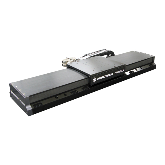
Summary of Contents for Aerotech PRO225LM Series
-
Page 1: Pro225Lm Hardware Manual
PRO225LM Hardware Manual Revision: 1.03.00... - Page 2 This manual contains proprietary information and may not be reproduced, disclosed, or used in whole or in part without the express written permission of Aerotech, Inc. Product names mentioned herein are used for identification purposes only and may be trademarks of their respective companies.
-
Page 3: Table Of Contents
3.3. Motor and Feedback Specifications 3.4. Limits, Marker, and Machine Direction 3.5. Motor and Feedback Phasing Chapter 4: Maintenance 4.1. Service and Inspection Schedule 4.2. Cleaning and Lubrication 4.3. Troubleshooting Appendix A: Warranty and Field Service Appendix B: Technical Changes Index www.aerotech.com... -
Page 4: List Of Figures
PRO225LM Accessory Tabletop Dimensions (-TT3, -TT6 Options) Figure 2-5: Dimensions for Stages without a Cable Management System (-CMS0 Option) Figure 2-6: Cantilevered Load Capability of PRO225LM Series Stages Figure 2-7: Stage Orientations Figure 3-1: Ground Connection Points for the -CMS0 Option... -
Page 5: List Of Tables
List of Tables Table 1-1: Model Numbers and Ordering Options Table 1-2: Environmental Specifications Table 1-3: PRO225LM Series Specifications (-0100 to -0400) Table 1-4: PRO225LM Series Specifications (-0500 to -1500) Table 2-1: Stage Mounting Surface Flatness Requirement Table 2-2: Stage to Mounting Surface Hardware... - Page 6 Table of Contents PRO225LM Hardware Manual This page intentionally left blank. www.aerotech.com...
-
Page 7: Safety Procedures And Warnings
N O T E : Aerotech continually improves its product offerings; listed options may be superseded at any time. All drawings and illustrations are for reference only and were complete and accurate as of this manual’s release. - Page 8 Safety PRO225LM Hardware Manual This page intentionally left blank. www.aerotech.com...
-
Page 9: Ec Declaration Of Incorporation
PRO225LM Hardware Manual Declaration of Conformity EC Declaration of Incorporation Manufacturer: Aerotech, Inc. 101 Zeta Drive Pittsburgh, PA 15238-2811 herewith declares that the product: PRO225LM Linear Stage is intended to be incorporated into machinery to constitute machinery covered by the Directive 2006/42/EC as amended;... - Page 10 Declaration of Conformity PRO225LM Hardware Manual This page intentionally left blank. www.aerotech.com...
-
Page 11: Chapter 1: Overview
The specifications in this manual pertain to the second generation of PRO LM stages. Second generation stages can be distinguished from their first generation counterparts by the second generation's curved hardcover. Contact Aerotech if you need a first generation manual. Table 1-1:... - Page 12 XY assembly; 5 arc sec orthogonality. Alignment to within 3 µm orthogonality for short travel stages. ALIGN-PA5Z XZ or YZ assembly with L-bracket; 5 arc sec orthogonality. Alignment to within 5 µm orthogonality for short travel stages. Chapter 1 www.aerotech.com...
-
Page 13: Environmental Specifications
1.2. Accuracy and Temperature Effects The accuracy specification of PRO225LM series stages is measured 25 mm above the table with the stage in an unloaded condition. The stage is assumed to be fully supported by a mounting surface meeting or exceeding the specification in Section 2.3. -
Page 14: Basic Specifications
PRO225LM Hardware Manual 1.3. Basic Specifications N O T E : Aerotech continually improves its product offerings; listed options may be superseded at any time. All drawings and illustrations are for reference only and were complete and accurate as of this manual’s release. -
Page 15: Table 1-4: Pro225Lm Series Specifications (-0500 To -1500)
3. Axis orientation for on-axis loading is listed. 4. Specifications are for single-axis systems measured 25 mm above the tabletop; performance of multi-axis system is payload and workpoint dependent (consult the Aerotech factory for multi-axis or non-standard applications). www.aerotech.com Chapter 1... -
Page 16: Vacuum Operation
Overview PRO225LM Hardware Manual 1.4. Vacuum Operation Aerotech can specially prepare the PRO225LM for operation in vacuum environments. Aerotech offers two vacuum preparation options; one for low vacuum (for use in atmospheric pressures to 10 torr) and one for high vacuum (preparation for environments from 10 to 10 torr). -
Page 17: Chapter 2: Mechanical Specifications And Installation
The brackets are red anodized aluminum (the only red anodized pieces Aerotech uses) that attach to the stage base on either side of the stage carriage. The rubber pads on the shipping brackets compress slightly to gently hold the carriage in place. Two shipping brackets are used on single axis and upper axis stages in a multi-axis stack, while four shipping brackets are used on lower axis stages in multi-axis stacks. -
Page 18: Figure 2-1: Shipping Brackets Used On Single Axis Stages Or Upper Axes Of Xy Systems
Shipping Brackets Used on Single Axis Stages or Upper Axes of XY Systems N O T E : After removing the lifting features or shipping brackets, retain them for future use. Do not transport or ship the PRO225LM without the lifting features or shipping brackets attached. Chapter 2 www.aerotech.com... -
Page 19: Figure 2-2: Pro225Lm Series Stage With Lifting Features
Standoff [QTY. 4] Figure 2-2: PRO225LM Series Stage with Lifting Features N O T E : After removing the lifting features or shipping brackets, retain them for future use. Do not transport or ship the PRO225LM without the lifting features or shipping brackets attached. -
Page 20: Dimensions
Mechanical Specifications and Installation PRO225LM Hardware Manual 2.2. Dimensions NOTES: Figure 2-3: PRO225LM Dimensions Chapter 2 www.aerotech.com... -
Page 21: Figure 2-4: Pro225Lm Accessory Tabletop Dimensions (-Tt3, -Tt6 Options)
6.6 THRU ALL 5.5 THRU ALL -TT3 MOUNTS THE FOLLOWING ADRS ADRT ALAR CCS190DR -150 -150 -100-SP* -240 -200 -200 -100-LP* -260 *SIDE MOUNT NOT AVAILABLE DIMENSIONS: MILLIMETERS Figure 2-4: PRO225LM Accessory Tabletop Dimensions (-TT3, -TT6 Options) www.aerotech.com Chapter 2... -
Page 22: Figure 2-5: Dimensions For Stages Without A Cable Management System (-Cms0 Option)
Mechanical Specifications and Installation PRO225LM Hardware Manual MOTOR/ENCODER FEEDBACK MOTOR POWER 6 MM AIR LINE CONNECTION CONNECTOR INTERFACE FORCER COOLING DIMENSIONS: MILLIMETERS Figure 2-5: Dimensions for Stages without a Cable Management System (-CMS0 Option) Chapter 2 www.aerotech.com... -
Page 23: Securing The Stage To The Mounting Surface
Section 2.2. for specific model mounting locations and dimensions. Table 2-2: Stage to Mounting Surface Hardware Mounting Hardware Typical Screw Torque M6 x 25 mm (or 1/4" x 1") SHCS with flat washers 7 N·m [5 ft·lb] www.aerotech.com Chapter 2... -
Page 24: Attaching The Payload To The Stage
N O T E : If your PRO225LM was purchased with Aerotech controls, it might have been tuned with a representative payload based on the information provided at the time of order. If the PRO225LM is started up without a payload, the servo gains provided by Aerotech with the shipment may not be appropriate and servo instability can occur. -
Page 25: Figure 2-6: Cantilevered Load Capability Of Pro225Lm Series Stages
PRO225LM Hardware Manual Mechanical Specifications and Installation Horizontal Side Offset Distance (mm) Figure 2-6: Cantilevered Load Capability of PRO225LM Series Stages Horizontal Side C.G. Horizontal Side Figure 2-7: Stage Orientations www.aerotech.com Chapter 2... -
Page 26: Speed Capability
The Motor Sizer application supplied by Aerotech at https://www.aerotech.com/resources/motor-sizer.aspx can be used to estimate allowable speeds and accelerations based on these parameters. Consult with an Aerotech Applications Engineer to specify the system configuration for optimum performance. -
Page 27: Chapter 3: Electrical Specifications And Installation
Electrical installation requirements will vary depending on product options. Installation instructions in this section are for PRO225LMs equipped with standard Aerotech motors intended for use with an Aerotech motion control system. Contact Aerotech for further information regarding products that are otherwise configured. -
Page 28: Motor And Feedback Connectors
N O T E : Refer to the other documentation accompanying your Aerotech equipment. Call your Aerotech representative if there are any questions on system configuration. N O T E : If using standard Aerotech motors and cables, motor and encoder connection adjustments are not required. -
Page 29: Table 3-1: Linear Motor Connector Wiring
Motor Phase A Motor Phase B Motor Phase C Motor Shield (EMI shield) Reserved Reserved Reserved Reserved Frame ground (motor protective ground) Mating Connector Aerotech P/N Third Party P/N Backshell ECK00656 Amphenol #17E-1726-2 Sockets [QTY. 4] ECK00659 ITT Cannon #DM53744-6 Connector ECK00657 ITT Cannon #DBMM9W4SA197 www.aerotech.com... -
Page 30: Table 3-2: Linear Motor Limit And Encoder Connector Wiring
+5 V power supply Sine Sine-N Reserved Common ground to limit switch Common ground to encoder power Reserved Reserved Negative (CCW) hardware limit Reserved Mating Connector Aerotech P/N Third Party P/N Backshell ECK00656 Amphenol 17-1726-2 Connector ECK00300 Cinch DB-25S Chapter 3 www.aerotech.com... -
Page 31: Table 3-3: Linear Motor Limit And Encoder Connector Wiring (-E3 Absolute Encoder Option)
Hall Effect sensor, phase C Reserved Reserved Reserved Reserved +5 V power supply Reserved Reserved Data+ Common ground Common ground Reserved Reserved Reserved Reserved Mating Connector Aerotech P/N Third Party P/N Backshell ECK00656 Amphenol 17-1726-2 Connector ECK00300 Cinch DB-25S www.aerotech.com Chapter 3... -
Page 32: Table 3-4: General Motor Connector Wiring (For Z Or T Axes)
16 [1.31] Motor Shield (EMI shield) 16 [1.31] Reserved Reserved Reserved Reserved Frame ground (motor protective ground) 16 [1.31] Mating Connector Aerotech P/N Third Party P/N Backshell ECK00656 Amphenol #17E-1726-2 Sockets [QTY. 4] ECK00659 ITT Cannon #DM53744-6 Connector ECK00657 ITT Cannon #DBMM9W4SA197 Chapter 3 www.aerotech.com... -
Page 33: Table 3-5: General Feedback Connector Wiring (For Z Or T Axes)
26 [0.129] Reserved Reserved Negative (CCW) hardware limit 26 [0.129] Reserved/Brake + 26 [0.129] 1. BRAKE pins On Z or T axis, otherwise Reserved Mating Connector Aerotech P/N Third Party P/N Backshell ECK00656 Amphenol 17-1726-2 Connector ECK00300 Cinch DB-25S www.aerotech.com Chapter 3... -
Page 34: Motor And Feedback Wiring
120 Ω COSINE-N +t° SINE 120 Ω SINE-N MARKER 120 Ω MARKER-N CLOCK+ 120 Ω CLOCK- DATA+ 120 Ω DATA- CASE CASE -E1 and -E2 Incremental Encoder Option -E3 Absolute Encoder Option Figure 3-2: Motor and Feedback Wiring Chapter 3 www.aerotech.com... -
Page 35: Figure 3-3: Motor And Feedback Wiring For A Typical Vertical Or Rotary Axis Stage
PRO225LM Hardware Manual Electrical Specifications and Installation Typical Aerotech Vertical or Rotary Axis Stage THIRD PARTY CONTROLLER 16 AWG 16 AWG MOTOR 16 AWG CONNECTIONS 16 AWG HALL A 26 AWG (typ) HALL B 26 AWG (typ) HALL C 26 AWG... -
Page 36: Motor And Feedback Specifications
Requires external pull-up to +5 V (10 kΩ recommended) Notes: If the PRO225LM is driven beyond the electrical limit, it will encounter a mechanical stop. Impacting the mechanical stop could cause damage to the stage even at low speeds. Chapter 3 www.aerotech.com... -
Page 37: Table 3-7: Pro225Lm Linear Motor Specifications (Blm-203-A)
5. All performance and electrical specifications ±10% 6. Maximum winding temperature is 125 °C. 7. Ambient operating temperature range 0°C - 25°C; consult Aerotech for performance in elevated ambient temperatures 8. All Aerotech amplifiers are rated Apk; use force constant in N·m/Apk when sizing. -
Page 38: Limits, Marker, And Machine Direction
PRO225LM Hardware Manual 3.4. Limits, Marker, and Machine Direction Aerotech stages are configured to have positive and negative "machine" directions. The machine direction defines the phasing of the feedback and motor signals and is dictated by the stage wiring (refer to Section 3.5. -
Page 39: Motor And Feedback Phasing
Motor phase voltage is measured relative to the virtual wye common point. Motor Phase A (ØA) Hall A Motor Phase B (ØB) Hall B Motor Phase C (ØC) Hall C Positive MOVE (Clockwise) Figure 3-5: Hall Phasing www.aerotech.com Chapter 3... -
Page 40: Figure 3-6: Analog Encoder Phasing Reference Diagram (-E1 Incremental Encoder)
720° 810° SIN-N 0° 90° 180° 270° 360° 450° 540° 630° 720° 810° COS-N 0° 90° 180° 270° 360° 450° 540° 630° 720° 810° MRK-N Positive MOVE (Clockwise) Figure 3-7: Encoder Phasing Reference Diagram (-E2 Incremental Encoder) Chapter 3 www.aerotech.com... -
Page 41: Chapter 4: Maintenance
Re-tighten loose connectors Replace or repair damaged cables Clean the PRO225LM and any components and cables as needed Repair any damage before operating the PRO225LM Inspect and perform an operational check on all safeguards and protective devices www.aerotech.com Chapter 4... -
Page 42: Cleaning And Lubrication
Cleaning If a solvent is necessary for cleaning the stage, Aerotech recommends using isopropyl alcohol. Harsher solvents, such as acetone, may damage the plastic and end caps on the bearing trucks. - Page 43 Check each mounting screw for full engagement by tightening the screw while holding the long side of a standard hex wrench. 10. Restore power to the stage; drive the stage table back to its original position to redistribute lubricants. www.aerotech.com Chapter 4...
-
Page 44: Figure 4-1: Endplate Cover Removal (Step 2)
Maintenance PRO225LM Hardware Manual Figure 4-1: Endplate Cover Removal (Step 2) Chapter 4 www.aerotech.com... -
Page 45: Figure 4-2: Hardcover Screw Removal (Step 3)
PRO225LM Hardware Manual Maintenance PRO165LM model shown. The number of screws securing the hardcover is model dependent. Figure 4-2: Hardcover Screw Removal (Step 3) www.aerotech.com Chapter 4... -
Page 46: Figure 4-3: Hardcover Removal (Step 3)
Maintenance PRO225LM Hardware Manual Figure 4-3: Hardcover Removal (Step 3) Chapter 4 www.aerotech.com... -
Page 47: Troubleshooting
Encoder (sine and cosine) signal connections (refer to Chapter 3 and Controller uncontrollably documentation). Motor Connections (refer to Chapter 3 and Controller documentation). Stage oscillates or Gains misadjusted (refer to the controller documentation). squeals Encoder signals (refer to the controller documentation). www.aerotech.com Chapter 4... - Page 48 Maintenance PRO225LM Hardware Manual This page intentionally left blank. Chapter 4 www.aerotech.com...
-
Page 49: Appendix A: Warranty And Field Service
Aerotech makes no warranty that its products are fit for the use or purpose to which they may be put by the buyer, whether or not such use or purpose has been disclosed to Aerotech in specifications or drawings previously or subsequently provided, or whether or not Aerotech’s... - Page 50 Aerotech's approval. On-site Warranty Repair If an Aerotech product cannot be made functional by telephone assistance or by sending and having the customer install replacement parts, and cannot be returned to the Aerotech service center for repair, and if Aerotech determines the problem could be warranty-related, then the following policy applies:...
-
Page 51: Appendix B: Technical Changes
Product update Product redesign Safety information updated 1.02.00 Order and part number specifications updated: Chapter 1 Added ThermoComp™ information 1.01.00 Revision changes have been archived. If you need a copy of this revision, contact Aerotech Global Technical Support. 1.00.00 www.aerotech.com Appendix B... - Page 52 Revision History PRO225LM Hardware Manual This page intentionally left blank. Appendix B www.aerotech.com...
-
Page 53: Index
EN ISO 12100 Encoder Specifications serial number service schedule Global Technical Support Shimming grease shipping brackets Shipping Brackets Hall-Effect Sensors Specifications Solution Humidity Specifications Speed Limitations inspect stabilize inspection schedule stage distortion isopropyl alcohol Support www.aerotech.com Index... - Page 54 Index PRO225LM Hardware Manual Symptom Technical Support Thermistor Specifications Unpacking and Handling the Stage vacuum vacuum guidelines Vibration Warranty and Field Service Index www.aerotech.com...
Need help?
Do you have a question about the PRO225LM Series and is the answer not in the manual?
Questions and answers