
Related Manuals for National Instruments PCI-232/2


Summary of Contents for National Instruments PCI-232/2
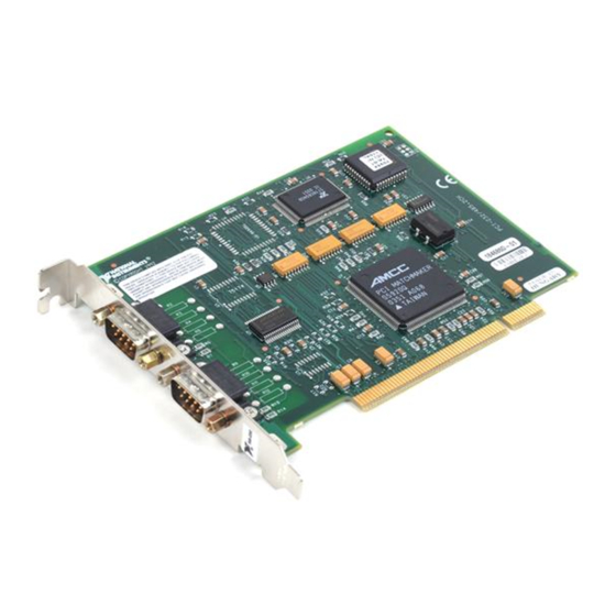
- Page 1 Serial Getting Started with Your PCI Serial Hardware and Software for Windows 95 PCI Serial for Windows 95 December 1997 Edition Part Number 321824A-01...
- Page 2 Singapore 2265886, Spain 91 640 0085, Sweden 08 730 49 70, Switzerland 056 200 51 51, Taiwan 02 377 1200, United Kingdom 01635 523545 National Instruments Corporate Headquarters 6504 Bridge Point Parkway Austin, Texas 78730-5039 USA Tel: 512 794 0100 © Copyright 1997 National Instruments Corporation. All rights reserved.
- Page 3 90 days from date of shipment, as evidenced by receipts or other documentation. National Instruments will, at its option, repair or replace software media that do not execute programming instructions if National Instruments receives notice of such defects during the warranty period.
- Page 4 Compliance FCC/DOC Radio Frequency Interference Compliance This equipment generates and uses radio frequency energy and, if not installed and used in strict accordance with the instructions in this manual, may cause interference to radio and television reception. Classification requirements are the same for the Federal Communications Commission (FCC) and the Canadian Department of Communications (DOC).
- Page 5 This device complies with the FCC rules only if used with shielded interface cables of suitable quality and construction. National Instruments used such cables to test this device and provides them for sale to the user. The use of inferior or nonshielded interface cables could void the user's authority to operate the equipment under the FCC rules.
-
Page 6: Table Of Contents
Optional Equipment ......................1-2 Serial Hardware Overview....................1-2 NI Serial Software Overview...................1-3 Optional Programming Tools ..................1-4 Using the Serial Hardware with Other National Instruments Products ......1-4 Chapter 2 Installation and Verification Install the NI Serial Software...................2-1 Install the PCI Serial Hardware ..................2-3 Verify the Installation ......................2-4... - Page 7 Termination ....................... C-4 Bias Resistors....................C-5 DTE vs. DCE ....................C-6 Appendix D Uninstalling the Serial Hardware and Software Removing the Hardware Information................D-1 Uninstalling the NI Serial Software ................D-3 PCI Serial for Windows 95 viii © National Instruments Corporation...
- Page 8 Null-Modem Cabling in a DTE-to-DCE Interface........C-7 Figure D-1. Selecting an Interface to Uninstall ............D-2 Figure D-2. Add/Remove Programs Properties Dialog Box........D-3 Figure D-3. Uninstallation Results................D-4 Figure E-1. Multi-Function Adapter Class in the Device Manager ......E-5 © National Instruments Corporation PCI Serial for Windows 95...
- Page 9 Physical Characteristics of the Eight-Port PCI Serial Boards ....A-2 Table A-4. Environmental Characteristics of the Serial Hardware......A-3 Table A-5. Software Characteristics ................. A-3 Table C-1. RS-232, RS-422, and RS-485 Features........... C-2 Table E-1. Standard DOS-Based Addresses............. E-4 PCI Serial for Windows 95 © National Instruments Corporation...
-
Page 10: About This Manual
About This Manual This manual contains instructions to help you install and configure the National Instruments serial hardware and the NI Serial software for Windows 95. The serial hardware covered by this manual includes the PCI-232/2, PCI-232/4, PCI-485/2, PCI-485/4, and PCI-232/8. This manual assumes that you are already familiar with Windows 95. -
Page 11: Conventions Used In This Manual
About This Manual • Appendix F, Customer Communication, contains forms you can use to request help from National Instruments or to comment on our products and manuals. • Glossary contains an alphabetical list and description of terms used in this manual, including abbreviations, acronyms, metric prefixes, mnemonics, and symbols. -
Page 12: Related Documentation
Corporation Customer Communication National Instruments wants to receive your comments on our products and manuals. We are interested in the applications you develop with our products, and we want to help if you have problems with them. To make it easy for you to contact us, this manual contains comment and configuration forms for you to complete. -
Page 13: Introduction
Install the Serial Hardware Verify the Installation Chapter 2 Troubleshooting Passes? Connect the Cables Chapter 3 Configure the Serial Port Learn About Transceiver Control Modes Chapter 4 Review Programming Requirements Write Application Program © National Instruments Corporation PCI Serial for Windows 95... -
Page 14: What You Need To Get Started
31 devices. Additionally, the PCI-232 and PCI-485 boards are available in a two-port version (PCI-232/2 and PCI-485/2), a four-port version (PCI-232/4 and PCI-485/4), and an eight-port version (PCI-232/8). The two-port versions use DB-9 connectors. The four-port versions use 10-position modular jacks to provide all four connections on a single back panel. -
Page 15: Ni Serial Software Overview
The NI Serial software includes the following components: • Device driver • Diagnostic test • Configuration utility The NI Serial software supports all National Instruments serial hardware, including all AT, PCI, and PCMCIA versions. © National Instruments Corporation PCI Serial for Windows 95... -
Page 16: Optional Programming Tools
Instruments Products You can use standard serial I/O functions in LabVIEW and LabWindows/CVI with any National Instruments serial interface, once you have installed the hardware and software. If you already have LabVIEW or LabWindows and want to use it with your serial hardware, refer to your LabVIEW or LabWindows documentation for information about serial I/O functions. -
Page 17: Installation And Verification
Double-click on the Add/Remove Programs icon in the Control Panel to launch the Add/Remove Programs applet. A dialog box similar to the one in Figure 2-1 appears. Figure 2-1. Add/Remove Programs Properties Dialog Box © National Instruments Corporation PCI Serial for Windows 95... -
Page 18: Figure 2-2. Ni Serial Setup Screen
Windows 95 should automatically detect your hardware and display one or more New Hardware Found dialog boxes, but you must make sure Windows Default Driver is selected and click on OK. PCI Serial for Windows 95 © National Instruments Corporation... -
Page 19: Install The Pci Serial Hardware
Figure 2-3 shows the installation of a PCI serial board. PCI Serial Board PCI Slot Personal Computer Figure 2-3. PCI Serial Board Installation © National Instruments Corporation PCI Serial for Windows 95... -
Page 20: Verify The Installation
Ports (COM & LPT) icon. Double-click on the Multi-function adapters icon as well as the Ports (COM & LPT) icon. Figure 2-4 shows an example of NI serial hardware that is installed properly. PCI Serial for Windows 95 © National Instruments Corporation... -
Page 21: Verify The Hardware Resources
Settings tab. The top of this page displays the serial number of the serial hardware, and the physical port number starting at 1. On all serial hardware, PORT1 refers to the top port, PORT2 refers to the next port down, and so on. © National Instruments Corporation PCI Serial for Windows 95... -
Page 22: Run The Diagnostic Test
To use the DB-9 connector with the four-port PCI serial boards, you need the 10-position modular jack to DB-9 cable available from National Instruments. You can also use a DB-25 connector with the four-port PCI serial boards by ordering the 10-position modular jack to DB-25 cable from National Instruments. -
Page 23: Figure 2-5. Db-9 Connector Pin Locations
485 Signal Pin 1 Pin 2 CTS+ (HSI+) Pin 3 RTS+ (HSO+) Pin 4 RXD+ Pin 5 RXD- Pin 6 CTS- (HSI-) Pin 7 RTS- (HSO-) Pin 8 TXD+ Pin 9 TXD- © National Instruments Corporation PCI Serial for Windows 95... -
Page 24: Figure 2-6. 10-Position Modular Jack Pin Locations
CTS+ (HSI+) Pin 8 RTS+ (HSO+) Pin 7 RXD+ Pin 6 RXD- Pin 5 CTS- (HSI-) Pin 4 RTS- (HSO-) Pin 3 TXD+ Pin 2 TXD- Pin 1 No Connect No Connect PCI Serial for Windows 95 © National Instruments Corporation... -
Page 25: Figure 2-7. Db-25 Connector Pin Locations
Pin 4 RTS- (HSO-) Pin 5 TXD+ Pin 6 CTS- (HSI-) Pin 7 RXD- Pin 8 Pin 20 RXD+ Pin 22 TXD- Pins not listed in this table are No Connect. © National Instruments Corporation PCI Serial for Windows 95... -
Page 26: Connecting Two-Wire Devices
Refer to Chapter 4, Using Your Serial Hardware, for information on setting the transceiver mode for two-wire communication. Refer to Appendix C, Serial Port Information, for more information on duplex architectures. PCI Serial for Windows 95 2-10 © National Instruments Corporation... -
Page 27: Configuration
Refer to the next section, Communication Port Settings, for more information. Note Transceiver modes apply to RS-485 interfaces only. For more information about transceiver modes, refer to Chapter 4, Using Your Serial Hardware. © National Instruments Corporation PCI Serial for Windows 95... -
Page 28: Communication Port Settings
Figure 3-1 shows the Port Settings tab. Figure 3-1. Port Settings Tab The following sections describe the port settings available on the Device Manager Port Settings tab. PCI Serial for Windows 95 © National Instruments Corporation... -
Page 29: Bits Per Second
Advanced button on the Port Settings tab. Figure 3-2 shows the Advanced Port Settings dialog box. Figure 3-2. Advanced Port Settings Dialog Box The following sections describe the advanced port setting options. © National Instruments Corporation PCI Serial for Windows 95... -
Page 30: Transceiver Mode
Note If you want your serial hardware ports to use the names COM1, COM2, COM3, or COM4, refer to the Common Questions section of Appendix E, Troubleshooting and Common Questions. PCI Serial for Windows 95 © National Instruments Corporation... -
Page 31: Using Your Serial Hardware
Use this mode in half-duplex systems where the (Data Terminal Ready) line must control the transmitter. In the -with-echo mode, the transmitter is tri-stated when the signal of the UART (Universal © National Instruments Corporation PCI Serial for Windows 95... -
Page 32: Two-Wire Mode: Dtr Controlled
For each port you want to control, write the control byte for the mode you want to select to the scratch register of the UART. Table 4-2 shows the control bytes for each mode. PCI Serial for Windows 95 © National Instruments Corporation... -
Page 33: Setting The Transceiver Mode With Deviceiocontrol
(unsigned long) listed in Table 4-3 for programming different transceiver modes. Table 4-3. DeviceIoControl Function Input Values DeviceIoControl Function Input Transceiver Mode Value Four-wire mode Two-wire mode: with echo Two-wire mode: controlled Two-wire mode: auto control TXRDY © National Instruments Corporation PCI Serial for Windows 95... -
Page 34: General Programming Requirements
Overviews and Win32 Reference. If you have LabVIEW or LabWindows and want to use it with your serial hardware, refer to your LabVIEW or LabWindows documentation for information about serial I/O functions. PCI Serial for Windows 95 © National Instruments Corporation... -
Page 35: Appendix A Specifications
Power Requirement (from PCI channel) PCI-485/2 +5 VDC 350 mA Typical 750 mA Maximum PCI-232/2 +5 VDC 50 mA Typical 100 mA Maximum 12 VDC 20 mA Typical ± 200 mA Maximum © National Instruments Corporation PCI Serial for Windows 95... -
Page 36: Table A-2. Physical Characteristics Of The Four-Port Pci Serial Boards
80 mA Typical ± 800 mA Maximum * The eight-port PCI serial board requires a cable, which is included in your kit, to convert the 68-position connector to eight DB-9 connectors. PCI Serial for Windows 95 © National Instruments Corporation... -
Page 37: Software Specifications
Maximum Serial Transfer Rate RS-485 460,800 bps* RS-232 115,200 bps* Space Required for NI Serial Software 1 MB * Actual speed may vary considerably from speed shown due to system and instrumentation capabilities. © National Instruments Corporation PCI Serial for Windows 95... -
Page 38: Forcing Windows 95 To Detect The Serial Hardware
Double click on Multifunction-Adapter class where Windows 95 lists the parent devices of the PCI ports, the serial interface. Select the National Instruments interface you are attempting to install, as shown in Figure B-1. © National Instruments Corporation... -
Page 39: Figure B-1. Port Selected In Device Manager
Repeat steps 6 and 7 until all serial board entries are removed. Then click on Refresh to force Windows 95 to detect the serial hardware and display the New Hardware Found dialog box. PCI Serial for Windows 95 © National Instruments Corporation... -
Page 40: Appendix C Serial Port Information
B. Differential voltage transmission creates a signal that is much more immune to noise as well as voltage loss due to transmission line effects. Thus, you can use RS-422 for much longer distances © National Instruments Corporation PCI Serial for Windows 95... -
Page 41: Table C-1. Rs-232, Rs-422, And Rs-485 Features
±25 V ±7 V +12 to –7 V Driver output 5 to 25 V 2 to 6 V 1.5 to 6 V 100 Ω 60 Ω Driver load > 3 kΩ PCI Serial for Windows 95 © National Instruments Corporation... -
Page 42: Serial Communication Issues
Because in a differential system each transmission line is composed of two separate wires, a full-duplex system is often referred to as a four-wire system. Figure C-1 shows a typical full-duplex system. © National Instruments Corporation PCI Serial for Windows 95... -
Page 43: Termination
The terminating resistor should match the characteristic impedance of the transmission line (typically 100–120 Ω). National Instruments offers an optional DB-9 RS-485 termination PCI Serial for Windows 95 © National Instruments Corporation... -
Page 44: Bias Resistors
200 mV, the threshold voltage for the receiver. You should install these resistors on only one node. © National Instruments Corporation PCI Serial for Windows 95... -
Page 45: Dte Vs. Dce
That is, a cable connected a computer to a modem by wiring pin 1 to pin 1, pin 2 to pin 2, and so on. This method is commonly known as straight-through cabling. PCI Serial for Windows 95 © National Instruments Corporation... -
Page 46: Figure C-5. Straight-Through Cabling In A Dte-To-Dce Interface
Figure C-6 shows null-modem cabling in a DTE-to-DCE interface. Rx D Rx D Pin 2 Pin 2 Tx D Tx D Pin 3 Pin 3 Figure C-6. Null-Modem Cabling in a DTE-to-DCE Interface © National Instruments Corporation PCI Serial for Windows 95... -
Page 47: Uninstalling The Serial Hardware And Software
Double-click the System icon under Start»Settings»Control Panel. The System Properties dialog box appears. Select the Device Manager tab. Click the View devices by type button. Double-click on the Multi-function Adapter icon. © National Instruments Corporation PCI Serial for Windows 95... -
Page 48: Figure D-1. Selecting An Interface To Uninstall
Appendix D Uninstalling the Serial Hardware and Software Select the National Instruments interface to remove from the list of interfaces as shown in Figure D-1. Figure D-1. Selecting an Interface to Uninstall Click the Remove button. In the Confirm Device Removal dialog box, click on the OK button to remove this interface or click on Cancel to cancel your request. -
Page 49: Uninstalling The Ni Serial Software
Add/Remove Programs applet. A dialog box similar to the one in Figure D-2 appears. This dialog box lists the software available for removal. Figure D-2. Add/Remove Programs Properties Dialog Box © National Instruments Corporation PCI Serial for Windows 95... -
Page 50: Figure D-3. Uninstallation Results
Figure D-3. Uninstallation Results Shut down Windows 95, power off your computer, and remove the PCI serial hardware. If you want to reinstall the hardware and software, refer to Chapter 2, Installation and Verification. PCI Serial for Windows 95 © National Instruments Corporation... -
Page 51: Troubleshooting And Common Questions
OK. 11. Restart Windows 95 so it can correctly assign resources to the serial port. Then refer to the Verify the Hardware Resources section of Chapter 2, Installation and Verification. © National Instruments Corporation PCI Serial for Windows 95... -
Page 52: Selecting Conflict-Free Resources
Chapter 2, Installation and Verification, to follow these troubleshooting steps. Verify the hardware resources. Verify that the National Instruments serial driver is installed and not the native Windows 95 serial driver. If either the serial hardware or file is missing, niserial.vxd reinstall the hardware and software. -
Page 53: Resolving Resource Conflicts With Legacy Boards
What do I do if the diagnostic test fails with an error? Refer to the troubleshooting sections of this manual for specific information about what might cause the test to fail. © National Instruments Corporation PCI Serial for Windows 95... -
Page 54: Table E-1. Standard Dos-Based Addresses
In most cases, Windows 95 does not assign names COM1 through COM4 to the serial hardware. Rather, it names the ports starting with COM5. If you assign any of the base addresses in Table D-1 to a National Instruments serial port, Windows 95 automatically changes the COM port name to the corresponding one listed in this table. -
Page 55: Figure E-1. Multi-Function Adapter Class In The Device Manager
How can I determine which version of the NI-Serial software I have installed? The Read Me file gives the version of the software. To read the file, select Read Me under Start»Programs»NI Serial Software for Windows 95. © National Instruments Corporation PCI Serial for Windows 95... - Page 56 BaudRate field of the DCB structure. What information should I have before I call National Instruments? When you call National Instruments, you should have the results of the Diagnostic test. Also, make sure you have filled out the hardware and...
-
Page 57: Customer Communication
Electronic Services Bulletin Board Support National Instruments has BBS and FTP sites dedicated for 24-hour support with a collection of files and documents to answer most common customer questions. From these sites, you can also download the latest instrument drivers, updates, and example programs. For recorded instructions on how to use the bulletin board and FTP services and for BBS automated information, call 512 795 6990. - Page 58 Telephone and Fax Support National Instruments has branch offices all over the world. Use the list below to find the technical support number for your country. If there is no National Instruments office in your country, contact the source from which you purchased your software to obtain support.
- Page 59 National Instruments for technical support helps our applications engineers answer your questions more efficiently. If you are using any National Instruments hardware or software products related to this problem, include the configuration forms from their user manuals. Include additional pages if necessary.
- Page 60 Complete a new copy of this form each time you revise your software or hardware configuration, and use this form as a reference for your current configuration. Completing this form accurately before contacting National Instruments for technical support helps our applications engineers answer your questions more efficiently.
- Page 61 Number of Serial Ports in System Built In ____________ Adapter Cards_______ Other boards in system ___________________________________________________________ Base I/O address of other boards ____________________________________________________ DMA channels of other boards _____________________________________________________ Interrupt level of other boards ______________________________________________________...
- Page 62 Documentation Comment Form National Instruments encourages you to comment on the documentation supplied with our products. This information helps us provide quality products to meet your needs. Title: Getting Started with Your PCI Serial Hardware and Software for Windows 95...
-
Page 63: Glossary
Data Communications Equipment or Data Circuit-Terminating Equipment direct memory access Data Terminal Equipment Data Terminal Ready (where the overscore denotes that the signal is active low) Electronic Industries Association electromagnetic interference Federal Communications Commission FIFO first-in-first-out © National Instruments Corporation PCI Serial for Windows 95... - Page 64 Receive seconds Transmit Transmit Ready (where the overscore denotes that the signal is active low) TXRDY UART universal asynchronous receiver/transmitter volts volts direct current PCI Serial for Windows 95 © National Instruments Corporation...
Need help?
Do you have a question about the PCI-232/2 and is the answer not in the manual?
Questions and answers