
Related Manuals for Enertech Bentone BG 450 M


Summary of Contents for Enertech Bentone BG 450 M
- Page 1 178 074 76 Providing sustainable energy solutions worldwide Installation- and maintenance instruction BG 450 M...
- Page 3 fi re or personal injury is avoided. – If another electrical connection is used than the one recommended by Enertech, there might be a risk of material damage or personal injury. – Notice should be carefully taken by the installer that no electrical cables or gas pipes get squeezed or damaged when installing or at service –...
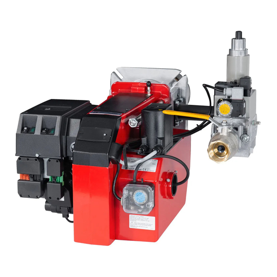
- Page 4 DESCRIPTION Components 11. Connection gas fi ttings 18. Switch l-ll 1. Flame cone 12. Air intake (For modulating burner: 2. Inner assembly 3. Fixing fl ange 13. Air damper Change-over switch manually- 14. Air pressure switch automatically) 4. Electric panel 15.
- Page 5 TECHNICAL DATA Type designation BG 450 Dimensions Length of burner Flange tube Measure A Standard The above dimensions are max. measurements. Depending on the components used, the measurements may vary. Out range Type Capacity Gas volume at a min. Gas volume at a max Max.
- Page 6 TECHNICAL DATA DIMENSIONS OF FLANGE 172 215 19 08-01...
- Page 7 SKELETON DIAGRAMS 1. Ball valve 6 a. When modulating operation is 5b, 7: Components not required required this valve is equipped 2. Filter according to EN 676. with controls for variable 3. Governor opening. 4. Pressure gauge with shut-off Required over 1200 kW according cock 6 b.
- Page 8 MOUNTING OF THE BURNER Fit the burner to the boiler by means When the burner head and the gas Ensure that the O-ring between the of 4 bolts M12. For fl ange and bolt fl ange have been fi tted to the boiler it gas assembly and the gas fl...
- Page 9 If there is no Plug-in contact (X4,X16) on the boiler, connect to the contact enclosed.
- Page 10 ELECTRIC EQUIPMENT Gas burner control: LGB22/LMG22/LME22 List of components Main switch Air pressure switch Gas burner control S11 Change-over switch, Aut.-Man. Power control S12 Change-over switch, Increase-Decrease Valve, leak tester, Dungs VPS504 S15 Control thermostat, 3-pole (only for 2-stage sliding) Ionization electrode Ignition transformer Operating fuse...
- Page 11 ELECTRIC EQUIPMENT Control diagnosis under fault conditions and lockout indication Gas burner control: LMG ... Diagnosis of cause of fault After lockout, the red fault LED is steady on. For reading the cause of fault, refer to the blink code given in the following table: Press lockout reset button Red LED on LED on (waiting time≥10 s)
- Page 12 ELECTRIC EQUIPMENT Control diagnosis under fault conditions and lockout indication Gas burner control: LME..Colour codes Colour code table for multi-coloured signal lamps (Light diodes) Status Colour codes Colours ○………………… Waiting time «tw», other waiting times Ignition phase, ignition checked •○...
- Page 13 ELECTRIC EQUIPMENT Control diagnosis under fault conditions and lockout indication Gas burner control: LME... Alarm control table Red fl ashing code Possible causes on signal lamp (LED) No fl ame at End of «TSA» Flashing 2 x – Defective or obscured fl ame monitor ••...
- Page 14 MEASURES AND CHECKS BEFORE START-UP, 2-STAGE- OR MODULATING BURNERS General rules Leakage control Care should be taken by the installer Note on 2-stage and modulating burn- MultiBloc to ensure that no electrical cables or ers that during the pre-purging period fuel/gas pipes are trapped or damaged the damper opens to the set value for air on stage 2 and just before the end...
- Page 15 MEASURES AND CHECKS BEFORE START-UP Inner assembly Town gas Inner assembly Natural gas, LPG Natural gas Inner assembly Biogas ((UV-detector) 172 205 18 12-01...
- Page 16 DETERMINATION OF GAS VOLUME FOR THE INSTALLATION Specifi cations on natural gas, town Net calorifi c value gas and bio gas vary. For more exact Gas quality kWh/Nm kJ/Nm kcal/Nm information please contact the gas Natural gas 10,3 37 144 8 865 distributor.
- Page 17 DUNGS COMBI BLOC WITH RATIO ADJUSTMENT MB-VEF BO1, 412 - 425 View 17 2 16 11 18 1. Electrical connection gas pressure switch mini 2. Electrical connection gas valve 3. Pressure switch mini 4. Flange connection inlet 5. Test point connection 1/8" before V 6.
- Page 18 TECHNICAL DATA WITH RATIO ADJUSTMENT - Max inlet pressure 360 mbar - Gas family 1 +2 +3 - Valves V class A group 2 in accordance with EN - Outlet pressure 0,5 - 100 mbar - Zero point adjustment N ±2 mbar - Governor class A group 2 in accordance with EN88 - Pressure switch DIN3398 TI - Ratio V P...
- Page 19 ADJUSTMENT OF GAS FLOW Damper motor, air volume Adjust the orange cam for min. load (about 5-10 on scale) Adjust the red cam for max. load (90° ) The blue cam is factory set for closed position during standstill The black cam has no function at modulating operation Gas valve (black) Max.
- Page 20 GENERAL INSTRUCTIONS Adjustment of burner A general rule is that the lower capacity Service the smaller the opening between The burner is from the factory pre-set Service should only be carried out by qualifi ed personnel. Replacement brake plate and combustion device. to an average value that must then be adjusted to the boiler in question.
- Page 21 GENERAL INSTRUCTION Flame monitoring and measure- Adjustemnt of max. gas pressure Adjustment of air pressure switch ment of ionisation current switch The air presure switch should stop the The burner is monitored according The burner is equipped with a max. burner if the air volume is reduced.
- Page 22 LEAKAGE CONTROL, DUNGS VPS 504 SERIE 2 Technical data ≤ Test volume 4,0 l ≈ Pressurre increase using motor pumps 20 mbar Backup (customer supply) 10A fast or 6.3A slow Fuse integrated in housing, replaceable T6,3L 250V (IEC 127-2/111) (DIN41662) Switching capacity Operating outputs SO1, SO2, SO4: 4A Faul output T7: 1A...
- Page 23 Electrical connection VPS 504 series 02 The VPS 504 is connected in series between the temperature regulator and the control box via a 7-pin plug tight connector. Connect the boiler connector to the connector socket of the VPS 504. untight For contact assignment of VPS 504 connector and heat generator connec- tor, refer to wiring diagram.
- Page 24 FINAL TEST OF THE INSTALLATION – Make repeated start attempts to Fault location, functional troubles ensure that the adjustments Trouble free operation is dependent function. on three factors: electricity, gas and air supply. Should there be any changes – Close the ball valve during in the ratio between these three factors operation to check that the gas there is a risk of break downs.
- Page 25 FAULT LOCATION GUIDE Gas burner To facilitate fault location we have drawn up a scheme The basis for trouble free operation can only be ensured showing the most frequent faults in a gas burner instal- by the correct combined effect of the three factors: electricity, gas fl...
- Page 26 REMEDY CAUSE The cable shoes have bad contact Improve the contact The ignition cables are damaged Replace The ignition transformer is damaged, no voltage Replace the transformer on the secondary side The ignition cable and the ionisation cable have Change been transposed.
- Page 27 REMEDY CAUSE Voltage lower than 185 V Contact the electricity authorities. Adjust the ignition electrodes, repole the ignition The ignition electrodes are disturbing the ionisation current transformer if necessary. Bad earthing Arrange for proper earthing. Phase and neutral transposed See wiring diagram and change. The burner locks out during pre-purge Air pressure switch defective or incorrectly adjusted The starting load is not correctly adjusted...
- Page 28 REMEDY CAUSE The ambient temperature of the gas relay is too high Heat insulate, max. 60° C. The ignition spark is too weak Check the transformer Bad combustion Bad draught conditions Check the chimney The fl ue gas temperature is too high The boiler is overloaded.
- Page 29 CE-0085 AU 0156 BG450 Enertech AB declares that the above-mentioned products Enertech AB erklärt hiemit, dass oben genannten Produkte mit comply with the following standards or other normative den folgenden Normen oder anderen normativen Dokumenten documents and meet applicable sections of the EU directive.
- Page 31 GENERAL INSTRUCTIONS FOR GASBURNERS Installation Follow standards and instructions applicable to the Check that the input pressure of the gas is correct installation of gas burners Check that the dampers of the boiler are open Ensure that the electric installation is made in Check that there is water in the system accordance with existing regulations Check that thermostats etc.
- Page 32 SERVICE AND INSPECTION CARD Installation Boiler Name: Type: Effi ciency kW: Address: Burner Type: Effi ciency kW: Installed by: Date: Date Flue gas Ionisa- gas/h Governor Pressure Effi ciency temp tion current Fire room Chimney Measure- Before After °C µ A mbar mbar % ment...
- Page 36 Enertech AB. P.O Box 309, SE-341 26 Ljungby. www.bentone.se, www.bentone.com...
Need help?
Do you have a question about the Bentone BG 450 M and is the answer not in the manual?
Questions and answers