
Related Manuals for Enertech Bentone B55 Series


Summary of Contents for Enertech Bentone B55 Series
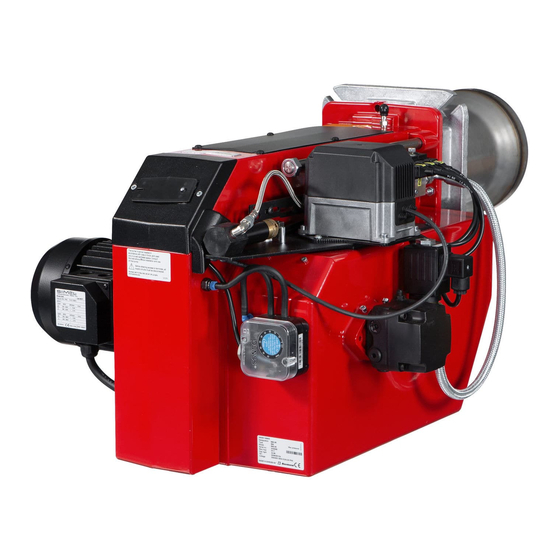
- Page 1 178 004 66-2 2016-08-11 Providing sustainable energy solutions worldwide Installation- and maintenance instruction B55, B65 Modell 2H, 2, 2R, 3R...
-
Page 3: Table Of Contents
Contents 01. GENERAL ........................... 5 Description B55/B65 ..............................5 Declaration of conformity ............................7 Manual ..................................8 Safety directions ................................ 8 02. TECHNICAL DATA ........................9 Type designation B55-2H/B55-2/B55-2R/B55-3R/B65-2H/B65-2/B65-2R/B65-3R ............ 9 Dimensions ................................. 9 Output range and nozzles recommended ........................ 9 Recommended nozzle and pressure ........................ -
Page 5: 01. General
01. GENERAL Description B55/B65 2 3 4 5 31a 27a 26a 27b 25a 22 23a Components Flame cone Solenoid valves Brake plate 23a. Connecting pipe Nozzle 25a. Solenoid valve bloc Stage 2 Nozzle assembly 26a. Nozzle assembly adjustment Ignition electrodes fixed Switch l-ll 27a. -
Page 6: Declaration Of Conformity
01. GENERAL Description B55/B65 19 18 22 27b 22 27b Components Ignition cables 25b. Solenoid valve bloc Stage 3 26a. Nozzle assembly adjustment Ignition transformer Photocell fixed Control box 26b. Nozzle assembly adjustment hydrauli Front plate, relay base Fan wheel 27a. -
Page 7: Manual
01. GENERAL Manual - The contents of this manual are to be observed by all who work for any reason on the unit and its appertaining system parts. - This manual is intended especially for authorised personnel. - This manual is to be regarded as part of the burner and shall always be available near the place of installation. -
Page 8: 02. Technical Data
02. TECHNICAL DATA Type designation B55-2H/B55-2/B55-2R/B55-3R/B65-2H/B65-2/B65-2R/B65-3R Dimensions Length of Flange Burner tube Burner tube Length of Flange Burner tube Burner tube burner tube Measure B Measure C Measure D burner tube Measure B Measure C Measure D Standard 1 Standard 2... -
Page 9: Working Field
02. TECHNICAL DATA Working field B55-2 14-67 kg/h 166-795 kW B55-2R B55-2H/B55-2 Measured (test) Output range kW B55-3R 14-64 kg/h 166-759 kW B55-3R Measured (test) Output range kW 24-99 kg/h 285-1174 kW Measured (test) Unbroken line is the approved working field as per EN267. 900 1000 1100 1200 Output range kW... -
Page 10: Nozzle Table
02. TECHNICAL DATA Nozzle table Pump pressure bar kg/h kW Mcal/h kg/h kW Mcal/h kg/h kW Mcal/h kg/h kW Mcal/h 2,75 10,24 10,73 11,21 11,67 3,00 11,16 11,71 12,23 12,73 3,50 13,03 13,66 14,27 14,85 4,00 14,89 15,62 16,31 16,97 4,50 16,75 17,57... -
Page 11: 03. Installation
03. INSTALLATION Acceptance inspection Ensure that everything is delivered and that there is no transport damage. If there is anything wrong with the delivery, please report it to the supplier. Any transport damage should be reported to the forwarding company. Preparations for installation Ensure that the size and capacity range of the burner are suitable for the boiler. -
Page 12: Burner Installation
03. INSTALLATION Burner installation Hole pattern Check that the hole pattern on the boiler matches the pattern on the burner flange. Flame head (160)* 165 (226)* 254-295 (160)* 210 (226)* 254-295 * The hole pattern can be reduced if the burner pipe is fitted from the front and the heels in the flange are ground off. -
Page 13: Basic Settings
04. BASIC SETTINGS Typical basic settings for B65-2H/B65-2/B65-2R/B65-3R Choice of nozzle Burner output= 770 kW B65-2H/B65-2/B65-2R Nozzle Stage 1 : 770 x 0,6 = 460 kW 460 / 11,86 = 38,8 kg/h Nozzle Stage 2 : 770 x 0,4 = 310 kW 310 / 11,86 = 26,1 kg/h According to the table of nozzles this gives the following nozzles: Stage 1 : 8,50 Gph... -
Page 14: Set Values For Nozzle Assembly B55
04. BASIC SETTINGS Set values for nozzle assembly B55 Set values for nozzle assembly B65 1000 1200 Set values for air damper B55 Set values for air damper B65 1000 1200 171 725 11 04-01... -
Page 15: Nozzle Assembly Regulation - Fixed Brake Plate
04. BASIC SETTINGS Nozzle assembly regulation – fixed brake plate Nozzle assembly regulation is used to achieve the most favourable pressure drop possible across the brake plate. Nozzle assembly regulation should be adjusted for Stage 2 output. Adjustment Adjust to the desired position on the scale (A) using the set screw (B) (turning anti-clockwise reduces the pressure drop and moves the brake plate outwards). -
Page 16: 05. Maintenance
05. MAINTENANCE Servicing the burner device Removal and fitting 1. Turn off the main power switch and disconnect the Eurostecker connectors from the burner. 2. Undo the nuts (E) and pull out the burner body on its guides. 3. Undo and remove the brake plate from the oil pipe. 4. -
Page 17: Servicing The Air Damper
05. MAINTENANCE Servicing the air damper Removal and fitting 1. Turn off the main power switch and disconnect the Eurostecker connectors from the burner. 2. Undo the nuts (E) and pull out the burner body on its guides. 3. Remove the intake grille from the air intake. 4. -
Page 18: 06. Instructions Pump Type Rsa 95 & 125
06. INSTRUCTIONS PUMP TYPE RSA 95 & 125 Technical data RSA 95 RSA 125 Viscosity range: 1,3-18,0 mm Pressure range at viscosity 1,3-1,8: 5,5-12,0 bar Pressure range at viscosity 1,8-18,0: 2,5-21,0 bar Oil temperature: -10 to+70°C Nozzle capacity at viscosity 4,3: 150-190 l/h 215-260 l/h Gearwheel capacity:... -
Page 19: Function Danfoss Rsa 95 - 125
06. INSTRUCTIONS PUMP TYPE RSA 95 & 125 Function Danfoss RSA 95 - 125 When the pump is started oil is drawn through the suction port "S" via filter "H" to the suction side of the gearwheel set "C". From here the gearwheel set pumps the oil to the pressure side and at the same time the oil becomes pressurized. -
Page 20: Suction Line Tables
06. INSTRUCTIONS PUMP TYPE RSA 95 & 125 Suction line tables 1-pipe system 1-pipe system Height Pipe diameter Height Pipe diameter ø12mm ø15mm ø20mm ø12mm ø15mm ø20mm With an underlying tank a 1-pipe- With an overlying tank a 1-pipe- system is not recommended system is not recommended. -
Page 21: Electric Equipment
ELECTRIC EQUIPMENT Wiring diagram LOA21.../LOA24... (B55-2H/B65-2H) 1(3) 171 435 47 2016-08-11... -
Page 22: Wiring Diagram Loa21
List of components LOA21.../LOA24... (B55-2H,R/B65-2H,R) Oil burner control Control thermostat, high/low Photoresistor Main switch 3-fas Operating fuse S20 Main switch 1-fas Ignition transformer Fuse Fuse Connection terminal board Lamp, low capacity Earth terminal Lamp, high capacity Plug-in contact ”Euro” burner Alarm signal 230V Plug-in contact ”Euro”, boiler Thermal overload protection... -
Page 23: Function Loa21
ELECTRIC EQUIPMENT Function 1. Switch on operating switch and twin thermostat The burner motor starts, an ignition spark is formed, the prepurge goes on till the prepurge period expires and the solenoid valve 1 opens (2). 2. Solenoid valve 1 opens Oil mist is formed and ignited. -
Page 24: 10. Fault Location
10. FAULT LOCATION Burner fails to start Possible causes Remedies Situation Motor runs Flame instability Check nozzle to burner head dimension and Burner pre-purges Incorrect head settings electrode position Check oil pressure Low oil pressure Adjust air damper Flame occurs Excess air Burner locks out Photocell not seeing light... -
Page 25: Spare Part List
OIL BURNERS MAINTENANCE INSTRUCTIONS General information If the burner starts but does not ignite Keep the boiler room clean. Ensure that the boiler Make an attempt to start the burner. room has permanent fresh air intake. Switch off before Never make close repeated start attempts. dismantling the oil burner. - Page 28 Enertech AB. P.O Box 309, SE-341 26 Ljungby. www.bentone.se, www.bentone.com...
Need help?
Do you have a question about the Bentone B55 Series and is the answer not in the manual?
Questions and answers