
Subscribe to Our Youtube Channel
Related Manuals for Enertech Bentone B 30 2A


Summary of Contents for Enertech Bentone B 30 2A
- Page 1 178 009 52 2014-01-21 Providing sustainable energy solutions worldwide Installation- and maintenance instruction B 30 2A...
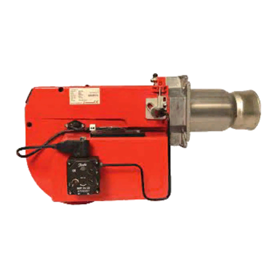
- Page 3 DESCRIPTION Components 1. Shrouded disc 9. Cover, inspection glass 17. Photo cell 2. Nozzle 10. Switch I-II 18. Air damper 3. Ignition electrodes 11. Switch 19. Air intake 4. Nozzle assembly 12. Fan wheel 20. Connecting pipe Stage 1 5. Ignition cable 13.
-
Page 4: Technical Data
TECHNICAL DATA Type designation B30A Dimensions ø108 160-190 Incl. lange A Burner tube Length of burner tube Measure B Output range and nozzles recommended Burner tube Oil capacity Capacity Recommended nozzle Recommended Pump pressure kg/h Mcal/h Angle Danfoss Monarch Stage 1 Stage 2 6,0-17,0 71-202... -
Page 5: General Instructions
GENERAL INSTRUCTIONS General rules Maintenance The boiler/burner should be examined The installation of an oil burner nozzles than older models. This increases the eficiency but also should be carried out in accordance regularly for any signs of malfunction with local regulations. The installer of or oil leakage. - Page 6 AIR ADJUSTMENT WITH DAMPER MOTOR The damper motor turns the damper Low capacity: Note! between 3 preset positions: fully Adjust the operating switch to high The blue cam is the limit position for closed, low capacity and high capa- capacity (II). fully closed damper and it is normally city.
- Page 7 MAINTENANCE OF OIL BURNER Warning: Before doing any service switch off power at the main switch and cut off the oil supply. Service of burner head Open the cover and disconnect the connecting pipes by loosening screw 1. Loosen or swing out the burner from the boiler.
- Page 8 (1)(2) * If the boiler is not equipped with wired contacts, connect the enclosed contacts to terminals X4 and X6 in accordance with wiring diagram. 1N ~ 50/60Hz 230 V...
-
Page 9: Electric Equipment
ELECTRIC EQUIPMENT List of components A1 Oil burner control B1 Photoresistor F1 Fuse H1 Lamp, low capacity H2 Lamp, high capacity H3 Lamp, lock-out signal 220 V M1 Burner motor M2 Damper motor SQN75.244A21B P1 Time meter, low capacity (optional) P2 Time meter, high capacity (optional) S1 Operating switch S2 Operating switch, high/low capacity... - Page 10 ELECTRIC EQUIPMENT Function Switch on operating switch and twin thermostat A spark is formed. The air damper motor opens the damper to low load position. The burner motor starts, the prepurge goes on till the prepurge period expires and the solenoid valve 1 opens (2) Solenoid valve 1 opens Oil mist is formed and ignited.
- Page 11 INSTRUCTIONS PUMP TYPE SUNTEC AT2 45C Technical data Viscosity range: 2-12 mm Pressure range: 8-25 bar Factory setting: Stage 1 10 bar Stage 2 20 bar Rated voltage of coil: 220/240V 50/60 Hz Oil temperature: max 60°C Components 1. Pressure adjustment Stage 1 2.
- Page 12 APPLICATIONS FOR SUNTEC AT2 45C By-pass solenoid Light oil. Blocking solenoid valve closed valve closed Nozzle low up to 45 l/h (approx. By-pass solenoid Blocking solenoid 460 000 kcal/h - 534 kW). valve open valve open One or two-pipe system. Pump operating principle Pressure gauge port...
-
Page 13: Nozzle Table
NOZZLE TABLE Pump pressure bar kg/h Mcal/h kg/h Mcal/h kg/h Mcal/h kg/h Mcal/h 0,40 1,33 1,41 1,49 1,56 0,50 1,66 1,76 1,86 1,95 0,60 2,00 2,12 2,23 2,34 0,65 2,16 2,29 2,42 2,54 0,75 2,49 2,65 2,79 2,93 0,85 2,83 3,00 3,16 3,32... - Page 14 NOZZLE TABLE Pump pressure bar kg/h Mcal/h kg/h Mcal/h kg/h Mcal/h kg/h Mcal/h 0,40 1,63 1,70 1,76 1,82 0,50 2,04 2,12 2,20 2,28 0,60 2,45 2,55 2,64 2,73 0,65 2,65 2,75 2,86 2,96 0,75 3,08 3,18 3,30 3,42 0,85 3,47 3,61 3,74 3,87...
-
Page 15: Fault Location
FAULT LOCATION Burner fails to start Situation Possible causes Remedies Motor runs Flame instability Burner pre-purges Check nozzle to burner head dimension Incorrect head settings and electrode position Low oil pressure Check oil pressure Flame occurs Excess air Adjust air damper Burner locks out Check that photocell is clean and unobstructed... - Page 16 EU direktiv. Enertech AB declares under sole responsibility that the above mentioned product is in conformity with the following standards or other normative documents and follows the provisions of applicable parts in the following EU Directives.
- Page 17 OIL BURNERS MAINTENANCE INSTRUCTIONS General information If the burner starts but does not ignite Keep the boiler room clean. Ensure that the boiler Make an attempt to start the burner. room has permanent fresh air intake. Switch off before Never make close repeated start attempts. dismantling the oil burner.
- Page 20 Enertech AB. P.O Box 309, SE-341 26 Ljungby. www.bentone.se, www.bentone.com...
Need help?
Do you have a question about the Bentone B 30 2A and is the answer not in the manual?
Questions and answers