
Related Manuals for Enertech Bentone B40A


Summary of Contents for Enertech Bentone B40A
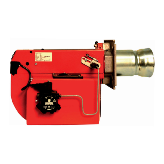
- Page 1 178 010 53-2 2016-04-15 Providing sustainable energy solutions worldwide Installation- and maintenance instruction B 40 A...
- Page 3 DESCRIPTION Components 1. Shrouded disc 8. Control box 15. Air adjustment 2. Nozzle 9. Reset button 16. Air damper 3. Ignition electrodes 10. Cover, inspection glass 17. Solenoid valve 4. Nozzle assembly 11. Fan wheel 18. Air intake 5. Ignition cable 12.
-
Page 4: Technical Data
TECHNICAL DATA Type designation B 40A ø114 Dimensions 200-230 Burner tube Length of burner tube Measure B Output range and nozzles recommended Burner tube Oil capacity Output Recommended Recommended Nozzle Pump pressure kg/h Mcal/h Angle Type 9,0-29,5 107-350 92-301 45°, 60° S, B, R, PLP 10-15 bar The net caloriic value of 11,86 kWh/kg for light oil has been used. -
Page 5: General Instructions
GENERAL INSTRUCTIONS General rules Condensation in chimney Maintenance The installation of an oil burner should A modern burner works with less ex- The boiler/burner should be exa- be carried out in accordance with local cess air and often also with smaller mined regularly for any signs of regulations. - Page 6 MAINTENANCE OF OIL BURNER Warning: Before doing any service switch off power at the main switch and cut off the oil supply. Service of burner head Open the cover and disconnect the connecting pipes by loosening screw 1. Loosen or swing out the burner from the boiler.
-
Page 7: Electric Equipment
ELECTRIC EQUIPMENT Oil burner control: LOA21... / LOA24.. List of components Wiring diagram A1 Oil burner control (1)(2) A2 Twin thermostat F1 Fuse, max. 10A H1 Alarm lamp H2 Signal lamp (optional) M1 Burner motor P1 Time meter (optional) R1 Photoresistor S3 Main switch T1 Ignition transformer Y1 Solenoid valve... - Page 8 ELECTRIC EQUIPMENT Function 1. Switch on operating switch and twin thermostat The burner motor starts, an ignition spark is formed, the prepurge goes on till the prepurge period expires and the solenoid valve opens (2). 2. Solenoid valve opens Oil mist is formed and ignited. The photocell indicates a lame. (1) The ignition spark goes out 15 s.
-
Page 9: Nozzle Table
NOZZLE TABLE Pump pressure bar kg/h Mcal/h kg/h Mcal/h kg/h Mcal/h kg/h Mcal/h 0,40 1,33 1,41 1,49 1,56 0,50 1,66 1,76 1,86 1,95 0,60 2,00 2,12 2,23 2,34 0,65 2,16 2,29 2,42 2,54 0,75 2,49 2,65 2,79 2,93 0,85 2,83 3,00 3,16 3,32... - Page 10 NOZZLE TABLE Pump pressure bar kg/h Mcal/h kg/h Mcal/h kg/h Mcal/h kg/h Mcal/h 0,40 1,63 1,70 1,76 1,82 0,50 2,04 2,12 2,20 2,28 0,60 2,45 2,55 2,64 2,73 0,65 2,65 2,75 2,86 2,96 0,75 3,08 3,18 3,30 3,42 0,85 3,47 3,61 3,74 3,87...
-
Page 11: Fault Location
FAULT LOCATION Burner fails to start Situation Possible causes Remedies Motor runs Flame instability Burner pre-purges Check nozzle to burner head dimension Incorrect head settings and electrode position Low oil pressure Check oil pressure Flame occurs Excess air Adjust air damper Burner locks out Check that photocell is clean and unobstructed... - Page 12 OIL BURNERS MAINTENANCE INSTRUCTIONS General information If the burner starts but does not ignite Keep the boiler room clean. Ensure that the boiler Make an attempt to start the burner. room has permanent fresh air intake. Switch off before Never make close repeated start attempts. dismantling the oil burner.
- Page 16 Enertech AB. P.O Box 309, SE-341 26 Ljungby. www.bentone.se, www.bentone.com...
Need help?
Do you have a question about the Bentone B40A and is the answer not in the manual?
Questions and answers