
Related Manuals for Enertech Bentone B55 Series


Summary of Contents for Enertech Bentone B55 Series
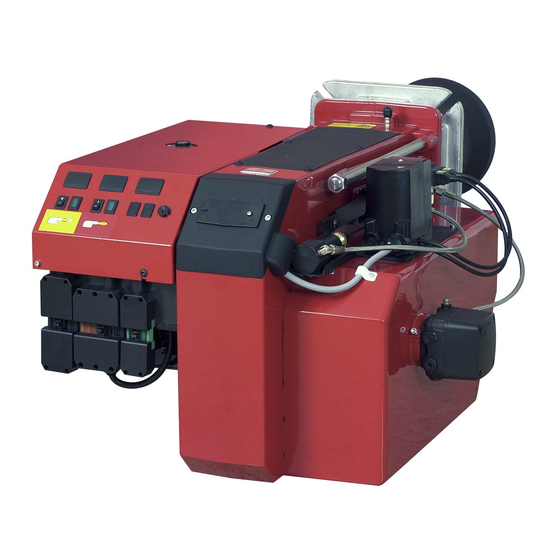
- Page 1 178 023 66-2 2016-11-24 Providing sustainable energy solutions worldwide Installation- and maintenance instruction B 55 / B 65...
- Page 3 01. GENERAL Description B55/B65 2 3 4 5 31a 27a 26a 27b 25a 22 23a Components Flame cone Solenoid valves Brake plate 23a. Connecting pipe Nozzle 25a. Solenoid valve bloc Stage 2 Nozzle assembly 26a. Nozzle assembly adjustment ixed Ignition electrodes Switch l-ll 27a.
- Page 4 01. GENERAL Description B55/B65 19 18 22 27b 22 27b Components Ignition cables 25b. Solenoid valve bloc Stage 3 Ignition transformer 26a. Nozzle assembly adjustment ixed Photocell Control box 26b. Nozzle assembly adjustment hydrauli Front plate, relay base 27a. Scale, air regulation Fan wheel 27b.
- Page 5 EU direktiv. Enertech AB declares under sole responsibility that the above mentioned product is in conformity with the following standards or other normative documents and follows the provisions of applicable parts in the following EU Directives.
-
Page 6: Safety Directions
01. GENERAL Manual - The contents of this manual are to be observed by all who work for any reason on the unit and its appertaining system parts. - This manual is intended especially for authorised personnel. - This manual is to be regarded as part of the burner and shall always be available near the place of installation. -
Page 7: Technical Data
02. TECHNICAL DATA Type designation B55-2H/B55-2/B55-2R/B55-3R/B65-2H/B65-2/B65-2R/B65-3R Dimensions Length of Flange Burner tube Burner tube Length of Flange Burner tube Burner tube burner tube MeasureB Measure C Measure D burner tube... - Page 8 02. TECHNICAL DATA Working ield B55-2 14-67 kg/h 166-795 kW B55-2R B55-2H/B55-2 Measured (test) Output range kW B55-3R 14-64 kg/h 166-759 kW B55-3R Measured (test) Output range kW 24-99 kg/h 285-1174 k W Measured (test) Unbroken line is the approved wor- king ield as per EN267. 200 300 700 800 900 1000 1100 1200...
-
Page 9: Nozzle Table
02. TECHNICAL DATA Nozzle table Pump pressure bar kg/h kW Mcal/h kg/h kW Mcal/h kg/h kW Mcal/h kg/h Mcal/h 2,75 10,24 10,73 11,21 11,67 3,00 11,16 11,71 12,23 12,73 3,50 13,03 13,66 14,27 14,85 4,00 14,89 15,62 16,31 16,97 4,50 16,75 17,57 18,35... -
Page 10: Installation
03. INSTALLATION Acceptance inspection Ensure that everything is delivered and that there is no transport damage. If there is anything wrong with the delivery, please report it to the supplier. Any transport damage should be reported to the forwarding company. Preparations for installation Ensure that the size and capacity range of the burner are suitable for the boiler. Power data on the data plate refer to the minimum and maximum... - Page 11 03. INSTALLATION Burner installation Hole pattern Check that the hole pattern on the boiler matches the pattern on the burner lange. Flame head d (160)* 165 (226)* 254-295 (160)* 210 (226)* 254-295 * The hole pattern can be reduced if the burner pipe is itted from the front and the heels in the lange are ground off. Installing the burner 1. Separate the burner body and the lange. 2.
-
Page 12: Basic Settings
04. BASIC SETTINGS Typical basic settings for B65-2H/B65-2/B65-2R/B65-3R Choice of nozzle Burner output= 770 kW Nozzle Stage 1 : 770 x 0,6 = 460 kW 460 / 11,86 = 38,8 kg/h B65-2H/B65-2/B65-2R Nozzle Stage 2 : 770 x 0,4 = 310 kW 310 / 11,86 = 26,1 kg/h According to the table of nozzles this gives the following nozzles: Stage 1 : 8,50 Gph Stage 2 : 6,00 Gph Pump pressure : 14 bar Basic settings Nozzle assembly Stage 2 = 15 B65-2H... - Page 13 04. BASIC SETTINGS Set values for nozzle assembly B55 Set values for nozzle assembly B65 1000 1200 Set values for air damper B55 Set values for air damper B65 1000 1200 171 725 11 04-01...
- Page 14 04. BASIC SETTINGS Nozzle assembly regulation – ixed brake plate Nozzle assembly regulation is used to achieve the most favourable pressure drop possible across the brake plate. Nozzle assembly regulation should be adjusted for Stage 2 output. Adjustment Adjust to the desired position on the scale (A) using the set screw (B) (turning anti-clockwise reduces the pressure drop and moves the brake plate outwards).
- Page 15 04. BASIC SETTINGS Damper motor 2-Stage The damper motor rotates the damper between three preset positions. These positions are controlled at the motor by micro-switches, the switching positions of which are set using the coloured cams. There is also a black cam, which controls the activation of solenoid valve 2.
- Page 16 04. BASIC SETTINGS Damper motor 3-Stage The damper motor rotates the damper between three preset positions. These positions are controlled at the motor by micro-switches, the switching positions of which are set using the coloured cams. There is also a black cam, which controls the activation of solenoid valve 2 and a green one which controls the activation of solenoid valve 3.
-
Page 17: Maintenance
05. MAINTENANCE Servicing the burner device Removal and itting 1. Turn off the main power switch and disconnect the Eurostecker connectors from the burner. 2. Undo the nuts (E) and pull out the burner body on its guides. 3. Undo and remove the brake plate from the oil pipe. 4. - Page 18 05. MAINTENANCE Servicing the air damper Removal and itting 1. Turn off the main power switch and disconnect the Eurostecker connectors from the burner. 2. Undo the nuts (E) and pull out the burner body on its guides. 3. Remove the intake grille from the air intake. 4.
- Page 19 06. INSTRUCTIONS PUMP TYPE RSA 95 & 125 Technical data RSA 95 RSA 125 Viscosity range: 1,3-18,0 mm Pressure range at viscosity 1,3-1,8: 5,5-12,0 bar Pressure range at viscosity 1,8-18,0: 2,5-21,0 bar Oil temperature: -10 to+70°C Nozzle capacity at viscosity 4,3: 150-190 l/h 215-260 l/h Gearwheel capacity: 225 l/h...
- Page 20 06. INSTRUCTIONS PUMP TYPE RSA 95 & 125 Function Danfoss RSA 95 - 125 When the pump is started oil is drawn through the suction port ”S” via ilter ”H” to the suction side of the gearwheel set ”C”. From here the gear- wheel set pumps the oil to the pressure side and at the same time the oil becomespressurized. The oil is led to cut-off and regulating valve ”V”...
- Page 21 06. INSTRUCTIONS PUMP TYPE RSA 95 & 125 Suction line tables 1-pipe system 1-pipe system Height Pipe diameter Height Pipe diameter ø12mm ø15mm ø20mm ø12mm ø15mm ø20mm With an underlying tank a 1-pipe- With an overlying tank a 1-pipe- system is not recommended system is not recommended. Two-pipe system Two-pipe system Height Pipe diameter Height...
-
Page 22: Electric Equipment
09. ELECTRIC EQUIPMENT Wiring diagram LMO24.255... (B55-2/B65-2/B55-2R/B65-2R) 1(3) 171 855 26 10-01... - Page 23 09. ELECTRIC EQUIPMENT List of components LMO24.255... (B55-2H/B65-2H/B55-2R/B65-2R) A1 Oil burner control S3 Operation thermostat B1 Photoresistor S4 Temperature limiter F1 Operating fuse S5 Micro switch for F2 Fuse hinged door F3 Fuse S6 Control thermostat, high/low Max loading K1 H1 Lamp, low capacity S7 Main switch 3-fas Connection A1,A2 / 95, 96 / 97, 98 H2 Lamp, high capacity...
- Page 24 ELECTRIC EQUIPMENT Colour codes LMO14/24 When the burner starts, three signal lights in the reset switch indicate the normal sequence, as well as provide indication if something ab- normal is happening in accordance with the following table: Preheater in operation Solid yellow Ignition switched on Flashing yellow Normal operation Solid green Operation, poor lame signal Flashing green Undervoltage...
-
Page 25: Fault Location
10. FAULT LOCATION Burner fails to start Situation Possible causes Remedies Motor runs Flame instability Check nozzle to burner head dimension and Incorrect head settings Burner pre-purges electrode position Low oil pressure Check oil pressure Excess air Adjust air damper Flame occurs Burner locks out Photocell not seeing light Check that photocell is clean and unobstructed... -
Page 26: Spare Part List
11. SPARE PART LIST 1(3) 171 745 01 08-01... - Page 27 11. SPARE PART LIST 1. Flame cone 11. Adjustment bar 30. Solenoid valve 919 947 02 304mm 119 728 0105 55-3, 65-3 118 450 01 bloc compl. 404mm 55-2, 65-2 55-3, 65-3 119 728 0205 118 290 01 504mm 119 728 0305 12.
- Page 28 11. SPARE PART LIST 58. Cover, 118 242 0205 41. Relay base inspection glass 114 942 00 LOA/LMO 915 596 00 59. Inspection cover 117 080 01 55-2, 65-2 60. Test nipple 118 053 01 42. Flange, 112 405 01 61.
- Page 32 Enertech AB. P.O Box 309, SE-341 26 Ljungby. www.bentone.se, www.bentone.com...
Need help?
Do you have a question about the Bentone B55 Series and is the answer not in the manual?
Questions and answers