Table of Contents
Advertisement
Quick Links
Advertisement
Table of Contents

Subscribe to Our Youtube Channel
Related Manuals for Enertech BG 450


Summary of Contents for Enertech BG 450
- Page 1 160 002 79 Installation- and maintenance instruction BG 450-2...
- Page 3 – If another electrical connection is used than the one recommended by Enertech, there might be a risk of material damage or personal injury. – Notice should be carefully taken by the installer that no electrical cables or gas pipes get squeezed or damaged when installing or at service –...
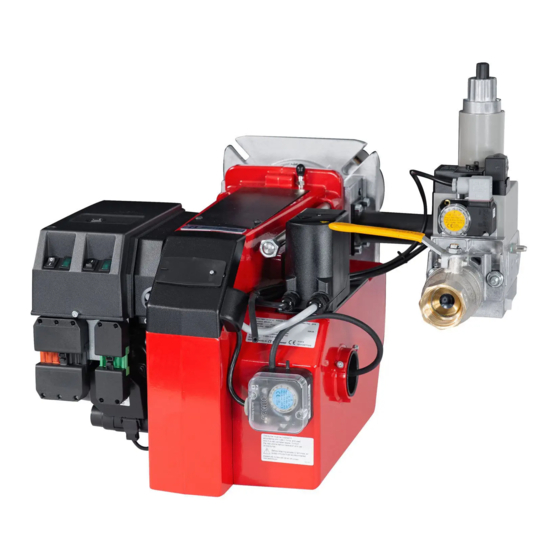
- Page 4 DESCRIPTION Components 11. Connection gas ittings 1. Flame cone 18. Switch l-ll 2. Inner assembly 12. Air intake (For modulating burner: 3. Fixing lange 13. Air damper Change-over switch manually- 4. Electric panel 14. Air pressure switch automatically) 15. Conical shield plate 19.
-
Page 5: Declaration Of Conformity
DECLARATION OF CONFORMITY TECHNICAL DATA Type designation BG 450 Dimensions (supplier´s name) ENERTECH AB (Address) Box 309, S-341 26 Ljungby, Sverige declare under our sole responsibility that the product Length of burner Flange (name, type or model, batch or serial number, possibly sources and number of items) - Page 6 TECHNICAL DATA REMEDY CAUSE The ambient temperature of the gas relay is too high Heat insulate, max. 60° C. DIMENSIONS OF FLANGE The ignition spark is too weak Check the transformer Bad combustion Bad draught conditions Check the chimney The lue gas temperature is too high The boiler is overloaded.
-
Page 7: Skeleton Diagrams
SKELETON DIAGRAMS REMEDY CAUSE Voltage lower than 185 V Contact the electricity authorities. Adjust the ignition electrodes, repole the ignition The ignition electrodes are disturbing the ionisation current transformer if necessary. Bad earthing Arrange for proper earthing. Phase and neutral transposed See wiring diagram and change. - Page 8 MOUNTING OF THE BURNER REMEDY CAUSE Fit the burner to the boiler by means When the burner head and the gas Ensure that the O-ring between the The cable shoes have bad contact Improve the contact of 4 bolts M12. For lange and bolt lange have been itted to the boiler it gas assembly and the gas lange will dimensions see technical data.
-
Page 9: Electric Equipment
ELECTRIC EQUIPMENT FAULT LOCATION GUIDE Gas burner control: LGB22/LMG22/LME22 Wiring diagram Gas burner The basis for trouble free operation can only be ensured To facilitate fault location we have drawn up a scheme by the correct combined effect of the three factors: showing the most frequent faults in a gas burner instal- electricity, gas low and combustion air. -
Page 10: Handing Over Of The Installation
ELECTRIC EQUIPMENT HANDING OVER OF THE INSTALLATION Gas burner control: LGB22/LMG22/LME22 – Make repeated start attempts to Fault location, functional troubles ensure that the adjustments Trouble free operation is dependent List of components function. on three factors: electricity, gas and air S4 Temperature limiter A1 Gas burner control supply. -
Page 11: General Instruction
GENERAL INSTRUCTION ELECTRIC EQUIPMENT Control diagnosis under fault conditions and lockout indication Flame monitoring and measure- Adjustemnt of max. gas pressure Adjustment of air pressure switch Gas burner control: LGB ment of ionisation current switch The air presure switch should stop the Lock-out and Control Programme Indication The burner is monitored according The burner is equipped with a max. -
Page 12: General Instructions
ELECTRIC EQUIPMENT GENERAL INSTRUCTIONS Control diagnosis under fault conditions and lockout indication Adjustment of burner A general rule is that the lower capacity Service Gas burner control: LMG ... the smaller the opening between The burner is from the factory pre-set Service should only be carried out Diagnosis of cause of fault by qualiied personnel. - Page 13 ADJUSTMENT OF MULTI-BLOC, MB-ZRDLE 405-420 ELECTRIC EQUIPMENT Adjustment of start gas low Flow adjustment 2-stage design Adjustment of governor Control diagnosis under fault conditions and lockout indication Adjust outlet pressure from governor For stage 1, loosen the lock screw Remove the protective cover c. Gas burner control: LME..
- Page 14 ELECTRIC EQUIPMENT MULTI-BLOC, MB-ZRDLE 405-420 Control diagnosis under fault conditions and lockout indication Gas burner control: LME... Alarm control table Red lashing code Possible causes on signal lamp (LED) No lame at End of «TSA» Flashing 2 x •• – Defective or obscured lame monitor –...
- Page 15 FUNCTION, 2-STAGE DESIGN MEASURES AND CHECKS BEFORE START-UP, 2-STAGE- OR MODULATING BURNERS Air adjustment Low load: Adjust the operating switch to full The damper motor turns the damper If the air volume needs changing: General rules Leakage control between three pre-set positions: fully load (ll).
- Page 16 MEASURES AND CHECKS BEFORE START-UP DETERMINATION OF GAS VOLUME FOR THE INSTALLATION Inner assembly Speciications on natural gas, town Net caloriic value Town gas gas and bio gas vary. For more exact Gas quality kWh/Nm kJ/Nm kcal/Nm information please contact the gas Natural gas 10,3 37 144...
Need help?
Do you have a question about the BG 450 and is the answer not in the manual?
Questions and answers