Table of Contents

Subscribe to Our Youtube Channel
Related Manuals for Bentone BG 550i M


Summary of Contents for Bentone BG 550i M
- Page 1 CR00264 178 130 80-2 2021-07-08 Providing sustainable energy solutions worldwide Installation- and maintenance instruction BG 550i/650i/700i/800i/950i M LMV37 MB-DLE 412-415 J/K IP40 Translation of the original instructions.
- Page 2 1~230V 1,0A 50Hz IP 20 Motor supply MADE IN SWEDEN BY 1. Manualer på övriga språk 1. Manuals in other languages 1. Manualer på andre sprog 2. www.bentone.com\ 2. www.bentone.com\download 2. www.bentone.com\download nedladdning or scan QR-code. eller scan QR-koden. eller scanna QR-koden.
-
Page 3: Table Of Contents
6.10 Gas nozzle BG 950 _______________________________ 39 6.11 UV detector _____________________________________ 40 6.12 Setting the air pressure switch _____________________ 41 6.13 Setting the min. gas pressure switch ________________ 42 6.14 Setting the power monitor _________________________ 43 6.15 Setting the max. gas pressure switch _______________ 44 Bentone... -
Page 4: General Information
• Burner pipes, fan wheels and air dampers may contain sharp edges. • The surface temperature of the burner’s components can exceed 60 °C. • Caution: The burner has moving parts, and there is risk of crushing injuries. 172 515 01 2018-01-02 Bentone... - Page 5 Open windows and doors. Close the gas ball valve. Warn residents; do not use doorbells. Evacuate the building. Notify the installer or gas supplier once the building has been evacuated. Bentone...
- Page 6 Delivery check • Make sure everything is delivered and the goods have not been damaged during transit. • If something is wrong with a delivery, report it to the supplier. • Transport damage must be reported to the shipping company. Bentone...
-
Page 7: Technical Data
A measure B measure C Standard 1 Standard 2 BG 550 Standard 3 Standard 1 BG 650 Standard 2 Standard BG 700 Long variant Standard BG 800 Long variant Standard 1 BG 950 172 525 59-2 2021-04-26 Bentone... - Page 8 (Ø 210) Ø 254-280 Ø 190 BG 650 (Ø 280) Ø320-380 (Ø 210) Ø 230 BG 700 (Ø 280) Ø320-380 (Ø 210) Ø 270 BG 800 (Ø 340) Ø420-490 (Ø 260) Ø 290 BG 950 172 525 59-2 2021-04-26/2 Bentone...
-
Page 9: Capacity Range
Grade of gas kWh/Nm MJ/Nm kcal/Nm Natural gas 34.02 8126 Natural gas 29.25 6986 Butane 32.5 116.09 27728 Propane 24.6 88.00 21019 Gas quantity and capacity vary according to grade of gas and connection pressure. 172 525 59-2 2021-04-26/3 Bentone... -
Page 10: Gas Categories, Approved Gases
2.3 Gas categories, approved gases Only dry gas is permitted for use. BG 550 BG 650, BG 800, BG 950 BG 700 172 525 59-2 2021-04-26/4 Bentone... -
Page 11: Electric Specification
Alt.2 The burner’s noise level can be reduced by connecting the burner’s air intake to the air duct that opens into an appropriate location. Installation must be done so it does not prevent air supply to the burner. 172 525 59-2 2021-04-26/5 Bentone... -
Page 12: Working Field
Do not exceed working field. mbar G30, G31 140-628 kW Do not exceed working field. BG 650-2, BG 650 M G20, G25 200-1125 kW G30, G31 200-1125 kW mbar Do not exceed working field. 1000 1100 1200 172 525 59-2 2021-04-26/6 Bentone... - Page 13 Do not exceed working field. 1000 1200 1400 1600 1800 2000 2200 2400 BG 950 M G20, G30, G31 500-3200 kW mbar G25 500-2800 kW Do not exceed working field. 1400 1900 2400 2900 3400 172 525 59-2 2021-04-26/7 Bentone...
-
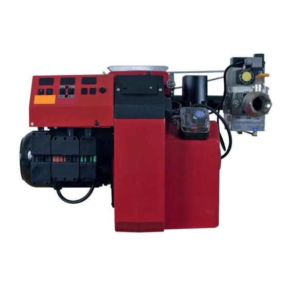
Page 14: Description Bg 550, Bg 650
2.6 Description BG 550, BG 650 172 525 59-2 2021-04-26/8 Bentone... - Page 15 Damper motor, air Ionisation electrode Connection gas fi ttings Electrical connection Air pressure switch Gas nozzle Fan house Motor Sight glass Measuring nipple, fan pressure AZL display for LMV automatic control unit Connection fl ange 172 525 59-2 2021-04-26/9 Bentone...
-
Page 16: Description Bg 700, Bg 800, Bg 950
2.7 Description BG 700, BG 800, BG 950 172 525 59-2 2021-04-26/10 Bentone... - Page 17 Shrouded disc Damper motor, air Ionisation electrode Connection gas fittings Electrical connection Air pressure switch Gas nozzle Fan house Motor Sight glass Measuring nipple, fan pressure Connection flange AZL display for LMV automatic control unit 172 525 59-2 2021-04-26/11 Bentone...
-
Page 18: General Instructions
Adjust the burner to appr. 20% excess air in accordance with the table. Check the flue gas temperature. Calculate the efficiency. Check also the actual gas volume on the gas meter so that the correct input is achieved. 172 515 03-2 Bentone... -
Page 19: Installation
(see Basic settings). Note that it is only a basic setting which should be adjusted once the burner has been started. If an electric connection other than the one recommended by Enertech is used, a risk of damage and injury can arise. 172 515 03-2 Bentone... -
Page 20: Fitting The Burner To The Boiler
Once the gas flange is fitted to the boiler, it is easy to lift the burner body up onto the guides. Assemble the burner in reverse order to its disassembly. Check the gas tightness. 172 525 60 2021-04-26 Bentone... -
Page 21: Handling And Lifting Instruction
4.8 Handling and lifting instruction 4.8.1 BG 550, BG 650 The lifting aid used here, is available as spare part. 172 515 34 Bentone... - Page 22 4.9 Handling and lifting instruction 4.9.1 BG 700 - BG 900 The lifting aids we use here are available as accessory, 172 515 37 Bentone...
-
Page 23: Inspection Of Gas Nozzle Before Commissioning
If the burner tube is the long variant, the gas nozzle must be removed from the connection tube and then inserted backwards into the fan housing (from the boiler) to enable maintenance of the brake plate, nozzle, electrodes, etc. 172 525 61-1 2021-04-26 Bentone... -
Page 24: Setting The Burner
See section 13.4 (LMV) for the setting procedure. 5.3 Setting the gas damper The position of the gas damper must be adjusted to achieve the desired minimum and maximum input power. See section 13.4 (LMV) for the setting procedure. 172 525 62-1 2021-04-26 Bentone... -
Page 25: Calculate Prepurge Time
((Q · 1,2) / 3600) ((200 · 1,2)/3600) Example B 9,5 · 5 285 seconds ((Q · 1,2) / 3600) ((500 · 1,2)/3600) 25 · 5 170 seconds Example C ((Q · 1,2) / 3600) ((2200 · 1,2)/3600) 172 525 62-1 2021-04-26/2 Bentone... -
Page 26: Recommended Excess Air When Using Default Setting
Lower heat value Hu at normal state 15°C and 1013.25 mbar Grade of gas kWh/Nm MJ/Nm kcal/Nm Natural gas 34,02 8126 Propane 29,25 6986 Butane 24,6 88,00 21019 32,5 116,09 27728 Town gas Biogas 21,60 5159 172 525 62-1 2021-04-26/3 Bentone... - Page 27 Temperature of gas at the gas meter [°C] Barometer reading [mbar] Pressure of gas at the gas meter [mbar] Factor calculated for multiplication with flow in Nm /h to arrive at actual flow in Nm Actual flow · 273+T 1013.25 172 525 62-1 2021-04-26/4 Bentone...
-
Page 28: Calculating The Quantity Of Gas Supplied
M = Quantity of gas consumed. V = Actual gas flow Calculation example: t = 1 min 10 s M = 4500 dm (litre) 4500 4.5 m 1000 0.0194 h 3600 ≈ 232 m 0.0194 172 525 62-1 2021-04-26/5 Bentone... -
Page 29: Service
Check the ionisation electrode (see chapter Gas nozzle). Replace if necessary. Fit the combustion assembly in reverse order. Press the burner together and lock using the nuts (B). Turn on the main power supply. Check/adjust the combustion. Check the gas tightness. 172 615 56 2018-08-10 Bentone... -
Page 30: Replacement Of Damper Motor, Air
Switch off the mains power.. position. If dampers do engage, the Mount the burner fully automatic control Turn on the mains power. unit will report an Check/adjust the combustion. error message. 172 615 56 2018-08-10 Bentone... - Page 31 172 615 56 2018-08-10 Bentone...
-
Page 32: Servicing Air Dampers
Lock the damper motor in position where the damper is almost engaged but still has a small air gap by the fan housing. Install the intake grille for the air intake. Press the burner together and lock using the nuts (B). Check/adjust the combustion. 172 615 56 2018-08-10 Bentone... -
Page 33: Replacement Of Damper Motor, Gas
When tightening screw (Y), ensure that the damper is in the closed position. Connect the damper motor cable to the automatic control unit. Fit the Euro plugs and turn on the mains power. Check / adjust combustion. 172 615 56 2018-08-10 Bentone... -
Page 34: Vibration
• Check all bolts and nuts for correct torque • Check fan wheel for damage and contamination. Change when dirty/ unbalanced • Check motor bearings. If worn change motor/bearings Use lid screw hole for sensor mounting 172 615 56 2018-08-10 Bentone... -
Page 35: Flame Monitoring And Ionisation Current Check
Max. DC 16…40 µA, flame display approx. 100% Threshold values when flame is supervised by an ionization probe: - Start prevention (extraneous Intensity of flame (parameter 954) ≥18% light) - Operation Intensity of flame (parameter 954) >24% X10-05,2 172 615 57 2018-08-10 Bentone... -
Page 36: Gas Nozzle Bg 550, Bg 650
Natural gas, Propane Biogas (UV detector) 6.8 Gas nozzle BG 550 LN A = 10 mm Front edge of brake plate A = Position of ionisation detector B = 3 mm B = Position of ignition electrode 172 525 63-1 2021-04-26 Bentone... -
Page 37: Gas Nozzle Bg 700, Bg 800
6.9 Gas nozzle BG 700, BG 800 Natural gas, Propane Natural gas ≈ 15-20 Propane Biogas (UV detector) 3-3,5 10-12 172 525 63-1 2021-04-26/2 Bentone... -
Page 38: Gas Nozzle Bg 950
6.10 Gas nozzle BG 950 Natural gas, LPG Distance electrode - brake plate Biogas (UV-sond) 172 525 63-1 2021-04-26/3 Bentone... -
Page 39: Uv Detector
- Simultaneous operation of QRA... and ionization probe is not permitted! Threshold values when fl ame is supervised by QRA...: - Start prevention (extraneous light) Intensity of fl ame (parameter 954) ≥18% - Operation Intensity of fl ame (parameter 954) >24% 172 525 64-1 2021-04-26 Bentone... -
Page 40: Setting The Air Pressure Switch
This is to ensure the reliable function of the burner. If breakdowns or interruptions occur, the air pressure switch is probably set to a too narrow position. Fit the protective cover, screw (Y). 172 525 65-1 2021-05-19 Bentone... -
Page 41: Setting The Min. Gas Pressure Switch
The tolerance on the scale for the min. gas pressure switch is approx. ±15%. Open the ball valve. Remove the pressure gauge and close the pressure outlet (X). Check the gas tightness. Fit the protective cover, screw (Y). 172 525 65-1 2021-05-19/2 Bentone... -
Page 42: Setting The Power Monitor
Test run the burner in the set power range. Remove the pressure gauge and close the pressure outlet. Fit the protective cover, screw (Y). Check the gas tightness. Gas pressure switch, air pressure switch Setting range: 2,5-50 mbar 5-150 mbar 172 525 65-1 2021-05-19/3 Bentone... -
Page 43: Setting The Max. Gas Pressure Switch
Set the max. gas pressure switch to this value by turning the scale. The tolerance on the scale for the max. gas pressure switch is approx. ±15%. Check the gas tightness. Remove the pressure gauge and close the pressure outlet (X). Fit the protective cover, screw (Y). 172 525 65-1 2021-05-19/4 Bentone... -
Page 44: Handing Over Of The Installation
• Is the circulation pump in operation? • Is there a supply of fresh air to the installation? • If integral components are of a different make from what is stated in this manual, see the enclosed loose-leaf. 172 615 04 Bentone... -
Page 45: Regulators
When connecting an external regulator of a type other than those which are installed on burners, see the manufacturer’s recommendations and the wiring diagram for burners. 172 615 58 2018-08-10 Bentone... -
Page 46: Sqm Damper Motor
50%, max. 3 min. continuously Angular adjustment Usable range max. 90° Degree of protection IP40 Rated resolution encoder monitoring 0.7° 0-position of actuator drive shaft Supply state 0 ±0.6° Environmental conditions: Temperature range -20...+60 °C Humidity <95% r.h. 172 525 66-1 2021-05-20 Bentone... - Page 47 • One-time bend when laying the cable: 2 x cable diameter • Always run the high-voltage ignition cables separate from the unit and other cables while observing the greatest possible distance. • The holding torque is reduced when the actuator is disconnected from power. 172 525 66-1 2021-05-20/2 Bentone...
- Page 48 50%, max. 3 min. continuously Angular adjustment Usable range max. 90° Degree of protection IP54 Rated resolution encoder monitoring 0.7° 0-position of actuator drive shaft Supply state 0 ±0.6° Environmental conditions: Temperature range -20...+60 °C Humidity <95% r.h. 172 525 66-1 2021-05-20/3 Bentone...
- Page 49 • One-time bend when laying the cable: 2 x cable diameter • Always run the high-voltage ignition cables separate from the unit and other cables while observing the greatest possible distance. • The holding torque is reduced when the actuator is disconnected from power. 172 525 66-1 2021-05-20/4 Bentone...
-
Page 50: Gas Train
Flanged versions: DMK 5065 and 5080 DMK 5065 and 5080 Environmental conditions: Temperature range -15...70 °C Humidity <95% r.h. Gas qualities No nonferrous materials. Suited for use with gases up to max. max. 0,1 vol. % H2S, dry 172 515 94 2018-08-10 Bentone... - Page 51 See image • When installing a gas damper, observe the direction of flow shown on the gas damper. • After working on a gas damper, check the gas tightness 172 515 94 2018-08-10 Bentone...
- Page 52 Air pressure switch Gas burner control LMV Pos. 5b, 7: Components not required according to EN 676. Required over 1200 kW according to EN 676 When Bio gas is used, Enertech shall always be contacted. 172 515 86 2018-08-02 Bentone...
-
Page 53: Multiblock Vgd40
Multi-block connection flange VGD40.65/SKP15/25 DN65 VGD40.80/SKP15/25 DN80 Environmental conditions: Temperature range -10...60 °C Humidity <95% r.h. Gas qualities No nonferrous materials. Suited for use with gases up to max. max 0,1 vol. % H2S, dry 172 515 90 2018-08-10 Bentone... - Page 54 The burner can also be fi tted with an additional gas pressure switch to monitor that the nozzle pressure does not get too high. 172 515 90 2018-08-10 Bentone...
- Page 55 Turning to right = higher regulator pressure Turning to left = lower regulator pressure Fit protective plug X. Possible output pressure range 15–120 mbar. Pressure is measured at the pressure outlet on SKP25. See section 10.2.2. 172 515 90 2018-08-10 Bentone...
- Page 56 > 4 mm. The impulse pipe must be protected again breakage and damage. If damage should occur, the impulse pipe must be replaced before the burner is put into operation again. 172 515 90 2018-08-10 Bentone...
-
Page 57: Multi-Bloc, Mb-Dle 412-420
Rp 1, 1¼, 1½, 2 MB-DLE 420 B01 S52 Rp 1, 1¼, 1½, 2 Environmental conditions: Temperature range -15...70 °C Gas qualities Suitable for gases of families 1, 2, 3 and other neutral gaseous media. 172 515 91 2018-08-10 Bentone... - Page 58 Electromagnet Filter housing Measuring connection output pressure Input fl ange Measuring connection G 1/8 after valve 1 (possible Measuring connection G 1/8 connection pressure on both sides) Gas pressure switch, min. Output fl ange Electrical connection for pressure switch Bentone...
- Page 59 12.1.3 Pressure taps Pressure outlets 1, 2, 3, 4, 5. Locking screw G 1/8 12.1.4 Electrical connection 172 515 91 2018-08-10 Bentone...
- Page 60 Turning to right = higher regulator pressure Turning to left = lower regulator pressure Possible output ranges 4–50 mbar for MB-D 412 and 20–50 mbar for MB-D 415 and 420. Pressure is measured at pressure outlet no. 6. See section 10.3.3. 172 515 91 2018-08-10 Bentone...
- Page 61 NB This adjustment is not suitable on burners with the LMV control system with a butterfl y gas valve. The adjustment of the amount of ignition gas is made here with the butterfl y valve. 172 515 91 2018-08-10 Bentone...
-
Page 62: Electric Equipment
• Installation will block burner operation and a manual restart will be required. Installation must be carried out pursuant to applicable regulations. 172 615 84-1 2021-05-19 Bentone... -
Page 63: Wiring Diagram
13.2 Wiring diagram 172 615 84-1 2021-05-19/2 Bentone... -
Page 64: Wiring Diagram Rwf 50:3
13.3 Wiring diagram RWF 50:3 172 615 84-1 2021-05-19/3 Bentone... -
Page 65: Wiring Diagram Rwf 50:2
13.4 Wiring diagram RWF 50:2 172 615 84-1 2021-05-19/4 Bentone... -
Page 66: Wiring Diagram Jumo 316
13.5 Wiring diagram Jumo 316 172 615 84-1 2021-05-19/5 Bentone... -
Page 67: List Of Compnents
Contact damper motor, gas SQN 13 AZL display for LMV automatic control unit Contactor with surge protection Transformer Fuse holder Branching point/ measureing point for ionisation LMV automatic control unit Quick release switch for regulator 172 615 84-1 2021-05-19/6 Bentone... -
Page 68: Lmv37 Automatic Control Unit
Example: Modulating gas burner The system components (display and operating unit, actuators) are connected directly to the LMV37.4... basic unit. All safety-related digital inputs and outputs of the system are monitored by a contact feedback network. 172 525 67 Bentone... -
Page 69: General Information
6.3 AT (DIN EN 60127 2 / 5) Mains supply: Input current depending on the operating state of the unit Under voltage Safety shutdown from operating position at mains voltage LMV37.400A2 Approx. AC 186 V Restart on rise in mains voltage LMV37.400A2 Approx. AC 195 V Bentone... - Page 70 X5-02 pin 2/3 POC *) RAST plug Function / Outputs pin number X3-05 pin 1 X4-02 pin 2/3 X6-03 pin 2/3 X8-02 pin 1/3 X7-01 pin 2/3 X7-02 pin 2/3 X3-05 pin 2 0° 0° 0° Legend to the sequence diagrams Bentone...
- Page 71 Postpurge time (t3) Evacuation of test space Atmospheric pressure test Filling of test space Gas pressure test Gas shortage waiting time Valve proving is performed depending on the parameter settings: Simultaneously with the prepurge time and/or the afterburn time. Bentone...
- Page 72 Only with fuel train Lo and 2 fuel valves Parameter 223: Repetition limit value gas pressure switch-min in connection with gas shortage program parameter 246 (phase 90) Max. drop-in/response time for air pressure switch Alternative to valve proving Alternative to pressure switch-max (Pmax) or POC Bentone...
- Page 73 0°/10% Position as supplied (0°) 90°/100% Actuator fully open (90°) Input/output signal 1 (ON) Input/output signal 0 (OFF) Input permissible signal 1 (ON) or 0 (OFF) Bentone...
-
Page 74: Connection And Internal Diagram
Protection earth (PE) Supply for fuel meter Shielding: Input fuel meter For shielding the cables on the VSD, refer to: • Siemens SED2 VSD Commissioning Manual (G5192), chapters 4 and 7, or • Danfoss Operation Manual VLT 6000 (MG60A703), chapter Installation Bentone... - Page 75 Speed feedback signal Speed feedback signal Signal reference PWM speed output PWM speed output Signal reference DC 24 V external DC 24V external Controller input 4...20 mA Controller input 4...20 mA Power source Power source Controller Analog Analog Controller Bentone...
-
Page 76: Operation
• For changing to a higher menu level (press button for 3…8 s) • For changing the operating mode (press button for >8 s) /reset - Enter in parameter setting mode - Reset in the event of fault - One menu level down Bentone... - Page 77 Figure 4: Meaning of display Fault status message Flame present Valve controlled Ignition controlled Fan motor controlled Oil preheater on Heat request from controllers Parameter setting mode Info mode Service mode h min s Actuator closing Actuator opening Unit of current display Bentone...
-
Page 78: List Of Phase Displays
Postpurge time (t3) (abortion when load controller ON) Ph80 Valve proving test evacuation time Ph81 Valve proving test time atmospheric pressure, atmospheric test Ph82 Valve proving filling test, filling Ph83 Valve proving time gas pressure, pressure test Ph90 Gas shortage waiting time Bentone... -
Page 79: Automatic Control Unit Levels
Change to normal Change to normal display display >3 s <8 s Info level /reset >3 s <8 s /reset or automatic return after timeout of Service level menu operation (parameter 127) >8 s >1 s Parameter level Parameter level Bentone... - Page 80 Basic unit Air-fuel ratio control curves (primary setting) /reset Bild 388e/1109 /reset Air-fuel ratio control /reset The following sections Actuator explain the operating philosophy behind the parameter levels using a number of examples. /reset Error histery /reset Process data Bentone...
- Page 81 Standardized speed Number of faults Error history: 701-725.01.Code 701. chronological error list index value of index Indexlista: 04 = error phase 01 = error code 05 = startup counter 02 = diagnostic code 06 = output 03 = error class Bentone...
- Page 82 Press button combination to display CodE When releasing the buttons, 7 bars appear the first of whishes. h min s Press to select a number or letter. h min s Press to confirm the value /reset Bentone...
- Page 83 The next bar starts flashing. h min s Complete the rest of the password according to the principle described. Example: Password consisting of 4 characters. min s After entery of the last character the password must be confirmed by pressing /reset Bentone...
-
Page 84: Setting The Automatic Control Unit
Press to select parameter 400 for initial commissioning and for setting air-fuel controll. /reset 201: appears fl ashing. h min s Press to go to the settings for air-fuel ratio control and parameter 201 for selecting the operating mode. Bentone... - Page 85 20 = gas modulating with pilot only when firing on gas (Gp1 mod fuel active) • 21 = gas modulating with pilot only when firing on gas (Gp2 mod fuel active) • 22 = oil modulating only when firing on oil (Lo mod fuel active) • Bentone...
- Page 86 Select your setting by pressing one of the buttons This manual describes Press to save the setting for parameter 542: VSD “0=VSD OFF” type /reset burners. Press: to return to parameter level. To the next parameter Back to the previous parameter Bentone...
- Page 87 Press simultaneously to set ignition position P0 of the fuel damper. Set a suitable fuel-air mixture so that the burner starts. Example: 30.0 h min s Press simultaneously and or to set ignition position P0 of the air actuator. Bentone...
- Page 88 To the next curvepoint P9 appears flashing. Curvepoint for high-fire. Same procedure as with P0 h min s Note: is pressed first, the display jumps to 90! Back to the previous curvepoint When curvepoint 9 is set, press to start the burner. Bentone...
- Page 89 This method makes the setting work easier and faster to complete. A more “correct” setting is obtained straight away. The process may need to be redone if the wrong input power was set for P9 initially. For this reason, be extremely careful when entering the first setting of P9. Bentone...
- Page 90 Phase Fan ramp up (fan motor = ON, safety valve = ON) h min s Phase Traveling to prepurge position h min s Phase Prepurging h min s Phase Traveling to ignition position h min s Bentone...
- Page 91 Phase Traveling to ignition position h min s Phase Preignition h min s Phase for first safety time (ignition transformer ON) h min s Phase for first safety time (ignition transformer OFF), preignition time OFF h min s Phase Interval 1 min s Bentone...
- Page 92 Low flame position P1 can only be set when symbol is no longer highlighted. The value is adopted from P0 For fuel, keep depressed, for air , h min s press to adjust the value. When symbol is no longer highlighted. Bentone...
- Page 93 The setting curve is therefore adjusted to the highest input power that the installation can handle. The desired input power is then set by entering how much of the maximum power is required. Bentone...
- Page 94 When symbol or is no longer highlighted, you can press ESC a second time. h min s Press to exit parameter level. h min s The settings for air-fuel ratio control by the LMV37.4... are now completed. Bentone...
- Page 95 0 = QRB / QRC 1 = ION / QRA Factory settings marked with bald text. When replacing detector flame between ionisation and UV-cell (QRA), no change to the setting parameters is required; simply disconnect and connect ionisation and UV-cell (QRA) respectively.. Bentone...
- Page 96 When the Purging in the lockout position function is used, the fan may only be powered via a contactor and must not be connected directly to LMV37.4 (X3-05 pin 1)! Bentone...
- Page 97 23 hours and 45 min of uninterrupted operation, followed by an automatic restart. When forced intermittent operation is inactivated the burner will run continuously. Forced intermittent operation is a standard feature. 239 Gas: Forced intermittent operation 0 = inactivate 1 = activated Factory settings marked with bald text. Bentone...
- Page 98 After login is complete, continue with the setting work as shown below. h min s Press to select parameter 400 for initial commissioning and for setting air-fuel ratio control /reset Identifi cation of start for setting the curve parameters. h min s Bentone...
- Page 99 The value is adopted from P0. For fuel, keep depressed, for air , Press to adjust the value. h min s When symbol is no longer highlighted, the next curvepoint P2 can be selected with To the next curvepoint back to the previous curvepoint Bentone...
- Page 100 If required, readjust the gas pressure. For fuel, keep depressed, for air , h min s Press to adjust the value. When symbol is no longer highlighted, the curve is set and it is possible to go on with the rest of the setting. Bentone...
- Page 101 /reset maximum capacity. Adjust the setting downwards or upwards using the buttons h min s Press to save the setting. /reset Press to return to parameter level. To the next parameter. Bentone...
- Page 102 Back to the previous Completing parameter parameterization of the curve When symbol is no longer highlighted, you can press ESC a second time. h min s h min s The warm settings for air-fuel ratio control by the LMV37.4... are now completed. Bentone...
-
Page 103: Backup And Restore
To continue with the setting work, you need to log into service engineer level. See 5.3.4. After login is complete, continue with the setting work as shown below. Press for parameter level 000. Press /reset Display: Parameter 050, flashes, index 00, and value 0 do not. /reset Display: Parameter bAC_UP /reset Bentone... - Page 104 If an errror occurs during the backup process, a negativ value is displayed. For error diagnostics, the cause of the error can be determined from the diagnostic code of error message 137 (see Error code list) Press four times until the top menu is displayed. Bentone...
- Page 105 After login is complete, continue with the setting work as shown below. Press for parameter level 000. Press /reset Display: Parameter 050, flashes, index 00, and value 0 do not. /reset Display: Parameter bAC_UP Press to select parameter rESstorE /reset Bentone...
- Page 106 Press to select the restore process. /reset Press to shift the value in change mode 1 position to the left. Display: Value 1 flashes To detect potential dispalay errors, the value is displayed 1 place shifted to the left Bentone...
-
Page 107: Fault Status Message, Display Of Errors And Info
The display shows current error code c: alternating with diagnostic code d: (refer to Flash code list). Example: Error code 4/diagnostic code 3 h min s When pressing for 1...3 s, rESEt appears on the display. /reset Bentone... - Page 108 SEr and then OPErAtE. >5 s /reset For a list of parameters, see table 5.3.3. h min s When the button is released, a change to info / service mode is made. >8 s /reset h min s Bentone...
- Page 109 The unit initiates safety shutdown. The display shows current error code c: alternating with diagnostic code d:. h min s Press 1...3 s, to return to the normal display. /reset Example: Error code 12 / diagnostic code 0 h min s Bentone...
- Page 110 Display: Parameter 701. flashes, index 01: and example value 201 does not. h min s Press to go to index 01: /reset Display: Parameter 701. does not flash, index 01: flashes, value 201 does not. h min s To the next index Back to the previous index. Bentone...
- Page 111 /reset Press to go to display mode. /reset Display: Value 56 (number of startup) h min s Press to return to the index. Display: Parameter 701. does not flash, index 05: flashes, characters ._._ h min s do not. Bentone...
- Page 112 To the next index Back to the previous index. When this display appears, you have reached the end of the error history. Display – End – appears flashing. h min s Press twice. HISt 700: for error history h min s Bentone...
-
Page 113: Dispaly Message Of Info
OFF UPr. h min s 15.7.3 Safety loop A unit whose safety loop and / or burner flange contact is open, and a controller ON signal is present, displays OFF S. h min s Bentone... -
Page 114: Resetting The Automatic Control Unit
Select another burner type than the one already selected by pressing one of the buttons Confirm this selection with The automatic control unit is now reset. /reset h min s Restart the setting process for the LMV automatic control unit as specified in 3.2.1. Bentone... -
Page 115: Manual Output
LoAd 0.0 means Manually OFF. As long as the Manual OFF is active, OFF appears on the normal display flashing. To deactivate and to change to automatic operation, press for 3 seconds. Then OFF appears without flashing in the display. Bentone... - Page 116 Manually OFF must not be used just to put a burner out of operation when doing mounting work, or when the burner is not ready for operation. The safety notes contained in chapter Safety notes must be observed! Bentone...
-
Page 140: Troubleshooting
Burner control faulty Replace Air pressure gauge incorrectly set or faulty Check the settings and reset, or replace No acknowledgement signal due to incorrect adjustment or Check the settings and realign. misalignment of the control motor cams. 172 615 06 2018-01-10 Bentone... - Page 141 Poor draught conditions. Check the chimney. Flue gas temperature too high. Boiler overloaded Decrease the gas volume, sweep the chimney if necessary. content too low. Choke the air supply. Check the boiler for any leakages. Choke the draught if too high. Bentone...
- Page 142 Flame at incorrect angle due to combustion head out of position. Check the combustion head and readjust. Condensation build up in boiler and chimney: Flue gas temperature too low or gas volume too low. Raise the flue gas temperature by increasing gas volume Insulate the chimney. Bentone...
-
Page 143: General Instructions For Gasburners
19. General instructions for gasburners 19.9.1 Installation Follow standards and instructions applicable to the Check that the burner is adapted to the gas quality in installation of gas burners. question. Ensure that the electric installation is made in accordance Check that the input pressure of the gas is correct. with existing regulations. - Page 144 Service- and inspection card Installation Boiler Name: Type: Efficiency kW: Address: Burner Type: Efficiency kW: Installed by: Date: Date gas/h Governor Fluegas Ionisation Pressure Efficiency temp current Fire Chimney room Measu- rement Before After °C µ A mbar mbar Small Flame Large Flame...
- Page 148 Enertech AB. P.O Box 309, SE-341 26 Ljungby. www.bentone.com...
Need help?
Do you have a question about the BG 550i M and is the answer not in the manual?
Questions and answers