
Related Manuals for Bentone BG 700-2 Biogas


Summary of Contents for Bentone BG 700-2 Biogas
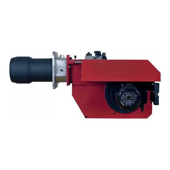
- Page 1 CR00301 178 151 80-2 2021-07-01 Providing sustainable energy solutions worldwide Installation- and maintenance instruction BG 700-2 Biogas BP230UVFR-S2 DMV-DLE 525/11 MVD 220/5 Translation of the original instructions.
- Page 2 1~230V 1,0A 50Hz IP 20 Motor supply MADE IN SWEDEN BY 1. Manualer på övriga språk 1. Manuals in other languages 1. Manualer på andre sprog 2. www.bentone.com\ 2. www.bentone.com\download 2. www.bentone.com\download nedladdning or scan QR-code. eller scan QR-koden. eller scanna QR-koden.
-
Page 3: Table Of Contents
5. Setting the burner __________________________________ 19 Setting the air pressure switch_____________________ 19 13. General instructions for gasburners _________________ 49 Setting the min. gas pressure switch _______________ 20 Skeleton diagram, biogas 2-stage burner ___________ 21 Adjusting the Gas Train ___________________________ 21 Bentone... -
Page 4: General Information
• Burner pipes, fan wheels and air dampers may contain sharp edges. • The surface temperature of the burner’s components can exceed 60 °C. • Caution: The burner has moving parts, and there is risk of crushing injuries. 172 515 01 2018-01-02 Bentone... - Page 5 Open windows and doors. Close the gas ball valve. Warn residents; do not use doorbells. Evacuate the building. Notify the installer or gas supplier once the building has been evacuated. Bentone...
- Page 6 Delivery check • Make sure everything is delivered and the goods have not been damaged during transit. • If something is wrong with a delivery, report it to the supplier. • Transport damage must be reported to the shipping company. Bentone...
-
Page 7: Technical Data
* The above dimensions are max. measurements. Depending on the components used, the measurements may vary. 2.1.1 Heat generator connection dimensions (Ø 280) Ø320-380 ***(Ø 210) Ø 230 BG 700 *** Dimensions when installing blast tubes from the inside of the heat generator. 172 525 07-3 Bentone... -
Page 8: Capacity Range
Gas quantity and capacity vary according to grade of gas and connection pressure. 2.3 Gas categories approved gases When using biogas, only dry gases with a max. 0.1% H S is used. The gas must contain a methane content of at least 50%. Bentone... -
Page 9: Working Field
Alt.2 The burner’s noise level can be reduced by connecting the burner’s air intake to the air duct that opens into an appropriate location. Installation must be done so it does not prevent air supply to the burner. Bentone... -
Page 10: Description Bg700-2
Air damper Time meter, stage 2 Fan house Air damper motor Contactor with thermal overload protection Shrouded disc Air pressure switch Control box Ignition electrode Fuse holder Gas train Nozzle Indicating lamp Stage 2 MultiBloc Ionisation electrode Switch l-ll Bentone... -
Page 11: General Instructions
Adjust the burner to appr. 20% excess air in accordance with the table. Check the flue gas temperature. Calculate the efficiency. Check also the actual gas volume on the gas meter so that the correct input is achieved. 172 515 03-2 Bentone... -
Page 12: Installation
(see Basic settings). Note that it is only a basic setting which should be adjusted once the burner has been started. If an electric connection other than the one recommended by Enertech is used, a risk of damage and injury can arise. 172 515 03-2 Bentone... -
Page 13: Handling And Lifting Instruction
4.6 Handling and lifting instruction 4.6.1 BG 700 - BG 900 The lifting aids we use here are available as accessory, 172 515 37 Bentone... -
Page 14: Mounting On The Boiler
For maintenance of the brake plate, nozzles, electrodes etc, when using a long design of the burner tube, you have to remove the nozzle assembly from the connecting pipe and move the assembly backwards in the fan housing (from the boiler). 172 515 38 2018-01-15 Bentone... -
Page 15: Inspection Of Gas Nozzle Before Commissioning
Re-assemble the burner in reverse order to that described above. When re- assembling, make sure that the O-ring located between the gas nozzle and the gas flange is in the correct position when the nozzle is re-fitted. Service position 172 515 39 2018-03-22 Bentone... -
Page 16: Leakage Control
The gas valve is energized and opens and flame is established. At the end of the safety time (2-3 sec.) the gas control locks out. The solenoid valve and the motor will be ”dead”. Remove the link from the gas pressure switch after the test is finished. Bentone... -
Page 17: Gas Nozzle
4.10 Gas nozzle Natural gas Propan Biogas (UV-detektor) Bentone... -
Page 18: Setting Damper Motor 2-Stage
90° to increase airfl ow. • Return the control switch to position I (low load) and check the combustion values. Solenoid valve High load (black) High load (red) Low load (orange) Closed air damper (blue) Release button 172 511 14-2 2021-05-03 Bentone... -
Page 19: Setting The Burner
This is to ensure the reliable function of the burner. If breakdowns or interruptions occur, the air pressure switch is probably set to a too narrow position. Fit the protective cover, screw (Y). 172 515 40 2018-01-15 Bentone... -
Page 20: Setting The Min. Gas Pressure Switch
The tolerance on the scale for the min. gas pressure switch is approx. ±15%. Open the ball valve. Remove the pressure gauge and close the pressure outlet (X). Check the gas tightness. Fit the protective cover, screw (Y). Bentone... -
Page 21: Skeleton Diagram, Biogas 2-Stage Burner
Adjust the air damper for correct combustion. At start-up, the safety valve opens and valve 1 gas flows VPS: Standard on burners with an output ≥ 1200 kW. Optional on burners with an output < 1200 kW. 172 515 72 2018-02-19 Bentone... -
Page 22: Gas Pressure Regulator Type Frs
Max. operating pressure 500 mbar Pressure regulator Class A Ambient temperature -15 °C … +70 °C Inlet pressure range 5 - 500 mbar Family 1 + 2 + 3 Outlet pressure range 2,5 - 200 mbar 172 515 66 2018-01-02 Bentone... - Page 23 Turn spindle to stop. Unscrew complete adjustment device B and remove spring C. Insert new spring D. Assemble complete adjustment device and adjust desired off-set. Screw on protective cap A. Stick adhesive label E onto typeplate. Attach lead seal. Bentone...
-
Page 24: Double Solenoid Valve Type Dmv
Max. operating pressure 500 mbar DMV 505-520/11 Pressure taps 1, 2, 3, 4 Sealing plug Screw plugs 1,2,3 may also be replaced by a measuring socket G 1/8 DIN ISO 228. Concealed connecting bore for system accessories. 172 515 67 2018-02-12 Bentone... - Page 25 1 - 5. Switch on firing system. Replace solenoid Important: Make sure that the solenoid no. and voltage are correct! Remount hydraulic brake or adjust-ing plate as described on page 6. ”Replacing the hydraulic brake or adjusting plate”, steps 7 -11. Bentone...
-
Page 26: Adjustment Of Gas Solenoid Valve Dungs Mvd
3. Turn the flow adjustment screw 2 to the right = gas flow Protection cover decrea-ses or to the left = gas flow Flow adjustment increases. Tighten the lock nut. Lock nut 172 515 71 2018-02-15 Bentone... -
Page 27: Recommended Excess Air When Using Default Setting
Lower heat value Hu at normal state 15°C and 1013.25 mbar EN676 Grade of gas kWh/Nm MJ/Nm kcal/Nm Natural gas 34.02 8126 Natural gas 29.25 6986 Propane 24.6 88.00 21019 Butane 32.5 116.09 27728 172 515 26 2018-01-11 Bentone... - Page 28 Temperature of gas at the gas meter [°C] Barometer reading [mbar] Pressure of gas at the gas meter [mbar] Factor calculated for multiplication with flow in Nm /h to arrive at actual flow in Nm Actual flow · 273+T 1013.25 Bentone...
-
Page 29: Calculating The Quantity Of Gas Supplied
= Time for a certain quantity of gas consumed by the burner. M = Quantity of gas consumed. V = Actual gas flow Calculation example: t = 1 min 10 s M = 450 dm (litre) 0.45 m 1000 0.0194 h 3600 0,45 ≈ 23.2 m 0.0194 Bentone... -
Page 30: Service
Fit the combustion assembly in reverse order. Press the burner together and lock using the nuts (B). Fit the Euro plugs and turn on the main power supply. Check/adjust the combustion. Check the gas tightness. 172 615 17 2018-01-15 Bentone... -
Page 31: Servicing Air Dampers
Re-install the damper motor and mounting plate on the air intake. Ensure that the damper shaft and control arm are connected correctly. Install the intake grille for the air intake. Press the burner together and lock using the nuts (B). Check/adjust the combustion. Bentone... -
Page 32: Replacement Of Damper Motor, Air
Ensure that the damper shaft and control arm are connected correctly. turned. This function facilitates an Connect the damper motor cable. exchange of damper motor. Fit the Euro plugs and turn on the mains power. Check/adjust the combustion. Bentone... -
Page 33: Vibration
Maximum vibration level are 5,0 mm/s • Check all bolts and nuts for correct torque • Check fan wheel for damage and contamination. Change when dirty/ unbalanced • Check motor bearings. If worn change motor/bearings Use lid screw for sensor mounting Bentone... -
Page 34: Flame Monitoring And Ionisation Current Check
Status LED shines yellow, the Fan LED flashes, and LEDs 2-6 show the flame signal strength. Each LED corresponds to 20% of the total flame signal. 5 lit LEDs correspond to 100% and 2 LEDs correspond to 40%. 172 615 69 20-10-15 Bentone... -
Page 35: Handing Over Of The Installation
• Is the circulation pump in operation? • Is there a supply of fresh air to the installation? • If integral components are of a different make from what is stated in this manual, see the enclosed loose-leaf. 172 615 04 Bentone... -
Page 36: Electric Equipment
Signals must be in different harnesses for safety reasons. Safety system as door switches, water level, pressure, temperature and other safety limiters must be installed in safety loop according to process. 172 615 86 Bentone... -
Page 37: Wiring Diagram Bp S2
10.2 Wiring diagram BP S2 Bentone... -
Page 38: List Of Components
Gas pressure switch, max Gas solenoid valve 1 overload protector Main switch Gas solenoid valve 2 Burner motor Ignition transformer Safety solenoid valve Damper Motor L&S Connection terminal board SQN75.494A21B Earth terminal UV-detector Mains connection and fuse in accordance with local regulations. Bentone... -
Page 39: Control
LED fl ashes during start-up. In Control mode, the Status LED shines yellow, the Fan LED fl ashes, and LEDs 2-6 show the fl ame signal strength. Each LED corresponds to 20% of the total fl ame signal. 5 lit LEDs correspond to 100% and 2 LEDs correspond to 40%. 172 615 70 201022 /1 Bentone... -
Page 40: Explanation Of The Different Sequence Modes
When lockout occurs, the LEDs indicate the cause. The control unit status is saved in the memory, even in the event of a power outage. By pressing the manual reset button on the control unit or remote reset. 172 615 70 201022 /2 Bentone... -
Page 41: Burnerpro Led Fault/Lock Code Table
11.4 BurnerPro LED fault/lock code table 172 615 70 201022 /3 Bentone... - Page 42 172 615 70 201022 /4 Bentone...
- Page 43 172 615 70 201022 /5 Bentone...
-
Page 44: Leakage Control Dungs Vps 504
(max. 26 s), the VPS 504 generates a fault. The red LED is lit as long as the contact is released by the regulator (heat requirement). After a short voltage drop during testing or during burner operation, an automatic restart is performed. 172 615 10 2018-01-15 Bentone... - Page 45 VPS 504. For contact assignment of VPS 504 connector and heat generator Lock-out Operation connector, refer to wiring diagram. Outlet Switching feature: No isolation between operating voltage circuit Operating voltage ~(AC) 230V 50Hz and control circuit. Bentone...
-
Page 46: Troubleshooting
Burner control faulty Replace Air pressure gauge incorrectly set or faulty Check the settings and reset, or replace No acknowledgement signal due to incorrect adjustment or Check the settings and realign. misalignment of the control motor cams. 172 615 06 2018-01-10 Bentone... - Page 47 Poor draught conditions. Check the chimney. Flue gas temperature too high. Boiler overloaded Decrease the gas volume, sweep the chimney if necessary. content too low. Choke the air supply. Check the boiler for any leakages. Choke the draught if too high. Bentone...
- Page 48 Flame at incorrect angle due to combustion head out of position. Check the combustion head and readjust. Condensation build up in boiler and chimney: Flue gas temperature too low or gas volume too low. Raise the flue gas temperature by increasing gas volume Insulate the chimney. Bentone...
-
Page 49: General Instructions For Gasburners
13. General instructions for gasburners 13.5.1 Installation Follow standards and instructions applicable to the Check that the burner is adapted to the gas quality in installation of gas burners. question. Ensure that the electric installation is made in accordance Check that the input pressure of the gas is correct. with existing regulations. - Page 50 Service- and inspection card Installation Boiler Name: Type: Efficiency kW: Address: Burner Type: Efficiency kW: Installed by: Date: Date gas/h Governor Fluegas Ionisation Pressure Efficiency temp current Fire Chimney room Measu- rement Before After °C µ A mbar mbar Small Flame Large Flame...
- Page 56 Enertech AB. P.O Box 309, SE-341 26 Ljungby. www.bentone.com...
Need help?
Do you have a question about the BG 700-2 Biogas and is the answer not in the manual?
Questions and answers