Table of Contents
Advertisement
Quick Links
Advertisement
Table of Contents

Related Manuals for hadewe Veloria MD


Summary of Contents for hadewe Veloria MD
- Page 1 Manual Veloria MD Art. 0775 FB 04-291 Rev. 2 Date: 23.01.2019...
-
Page 2: Table Of Contents
Directory Foreword Safety Instructions Cleaning & Disinfection Getting to Know the Unit Before First Use Area of Application Operation Operating Steps Working Positioning Suction Exchange Micro Filter Exchange Control Unit Filter Clamping the Bur/Tool Setting up the Speed Foot Switch Maintenance &... -
Page 3: Foreword
Short description of functions The Veloria MD is a device for the treatment of callus and nails. The handpiece is com- patible with rotating tools such as diamond polishers, steel cutters and ceramic cutters. -
Page 4: Safety Instructions
Safety Instructions The equipment should only be used by trained operators. The installation of the working area has to cor- respond to the relevant regulations. Set up the unit in such a way, that the air slits are not blocked and the extracted air can escape well. To avoid the risk of electrocution only connect the device to the mains power supply. - Page 5 Safety Instructions Prevent your hair from wrapping itself around moving parts. If applicable, wear a hair net. When working with materials, which might cre- ate dust or moisture, use a drilling unit with suction or spray technique. Wear a nose and mouth protection.
- Page 6 Safety Instructions • the inserted tool sits properly in the chuck and will not cant/jam while clamping it, • the tool is approved for using it at the max speed (see manufacturer’s instructions), or • only use the speed required by the instru- ment, •...
- Page 7 Safety Instructions Always follow the operating instructions. Do not carry out any repairs, modifications or mainte- nance work yourself. This is only to be accom- plished by an authorized specialist. The mains cable may also only be changed by the manu- facturer, or an authorized specialist.
-
Page 8: Cleaning & Disinfection
Cleaning & Disinfection The device is designed to be compatible with rotating in- struments which do not penetrate the skin or mucosal or inadvertently may still cause injuries. For this application please adhere to the cleaning and disinfection instructions provided be- low. -
Page 9: Getting To Know The Unit
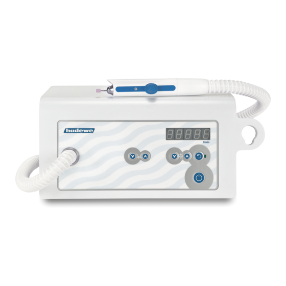
Getting to Know the Unit 1 decrease the suction power 2 increase the suction power 3 reduce the speed 4 increase the speed 5 display of speed/suction level 6 change direction of rotation 7 LED is ON during reverse rotation and in standby 8 main switch 9 switching ON/OFF the unit (standby) -
Page 10: Before First Use
Before First Use Please read through the instructions Operation carefully before using the unit and The working area must conform to carefully note the safety advice. the conditions described. Set up the Always keep this manual accessible unit in such a way, that the air slits to any users of the drill. - Page 11 Before First Use If you have a foot switch, insert its Take up the handpiece. Should the plug into the port on the right of the handpiece be twisted by the hose device which displays this symbol you can adjust that at the control unit.
-
Page 12: Use
Operating Steps tion power you can start working. If you want to take a break or finish In the following section the order in the job, press the standby button which you should use the device is (9). The handpiece motor and suc- described. -
Page 13: Working Positioning
Work Positioning The following images are examples of how to work on various parts of the foot. Always make sure that the foot is firmly gripped and that you can work freely and without strain. -
Page 15: Suction
Suction Pull out the lid of the dust chamber and remove the old filter. Hold the Switch on the suction with button filter in the middle to prevent it from (2). The suction output can be regu- bending and sliding off (see picture lated in 5 levels. -
Page 16: Clamping The Bur/Tool
Foot Switch (art. 0970) Commencement of foot switch Only use the original hadewe foot switch to avoid damages. Insert the plug of the foot switch into the socket with this symbol Function of the foot switch... -
Page 17: Maintenance & Care
Maintenance & Care Cleaning the Chuck In the process of time, some dirt might collect itself within the hand- piece, and might affect its functions. Therefore, the chuck has to be cleaned monthly. How to remove the chuck Screw off the top of the handpiece To assemble the chuck, follow the with the spanner shown in the pic- steps in reverse order. -
Page 18: Maintenance Overview
Maintenance & Care Rinse the chuck very well, and make sure you let it dry well after- wards. Cover your index finger with a very little amount (just a drop) of oil and rub in between your thumb and index finger. Dab off the oil until your fingers is only covered with a very thin film of oil. -
Page 19: Handling Instructions
In cases in which a down. A second disadvantage is the rust infestation was found within the... -
Page 20: Troubleshooting
The bur/tool itself can be tested with Footswitch is used constantly or the hadewe Bur Shaft Tester faulty. → Pull out the socket of (art. 4990) to see if it is bent. the foot switch to see if this is the cause. -
Page 21: Technical Data
Technical Data 0775 Veloria MD Accessories & Spare Parts total weight: 2,7 kg art. dimension: W273xH142xD186 mm 5179 micro filter input: 100 V - 240 V~, 50/60 Hz 3752 control unit filter power consumpt.: 1A(100V)-0,5A(240V) 0970 foot switch fuse primary: F1, F2: 4 A time delay... - Page 22 For disposal of this unit out The protective ground conductor is of Germany, please contact the site not connected to touchable conduc- where you bought this hadewe tive parts. product. Necessary function inspection: speed, display, on/off, suc- Note for the disposal of the device/ tion/spray, clamping system.
- Page 23 Technical Data Symbols Caution! Important note! Follow instructions for use! Temperature limit (indicates the lower and upper tem- perature limit) Air pressure: permissible range Air humidity: permissible range Keep dry! ON/OFF button (standby) (no disconnection from main power supply) change direction of rotation suction rotation alternating current...
- Page 24 Technical Data Information on electromagnetic compatibility in accordance with DIN EN 60601-1-2 Guidance and Manufacturer's Declaration – Electromagnetic Emissions The device is suitable for use in the specified electromagnetic environment. The customer and/or the user of the pa-on should assure that it is used in an electromagnetic environment as described below: Emissions Test Compliance...
- Page 25 Technical Data Guidance and Manufacturer's Declaration – Electromagnetic Immunity IEC 60601-1-2 The device is suitable for use in the specified electromagnetic environment. The customer and/or the user of the device should assure that it is used in an electromagnetic environment as described below: Immunity Test IEC 60601 Test...
- Page 26 Technical Data Guidance and Manufacturer's Declaration – Electromagnetic Immunity IEC 60601-1-2 The device is suitable for use in the specified electromagnetic environment. The customer and/or the user of the device should assure that it is used in an electromagnetic environment as described below: Immunity Test IEC 60601 Test Level...
- Page 27 Technical Data a) Field strengths from fixed transmitters, such as base stations for radio (cellular/cordless) telephones and land mobile radios, amateur radio, AM and FM radio broadcast, and TV broadcast cannot be predicted theoretically with accuracy. To assess the electromagnetic environment due to fixed RF transmitters, an electromagnetic site survey should be consid- ered.
- Page 28 GmbH Grambartstraße 10 30165 Hannover Germany info@hadewe.de www.hadewe.de...
Need help?
Do you have a question about the Veloria MD and is the answer not in the manual?
Questions and answers