
Related Manuals for Pepperl+Fuchs IDENT-I system P IPT FP Series

Summary of Contents for Pepperl+Fuchs IDENT-I system P IPT FP Series
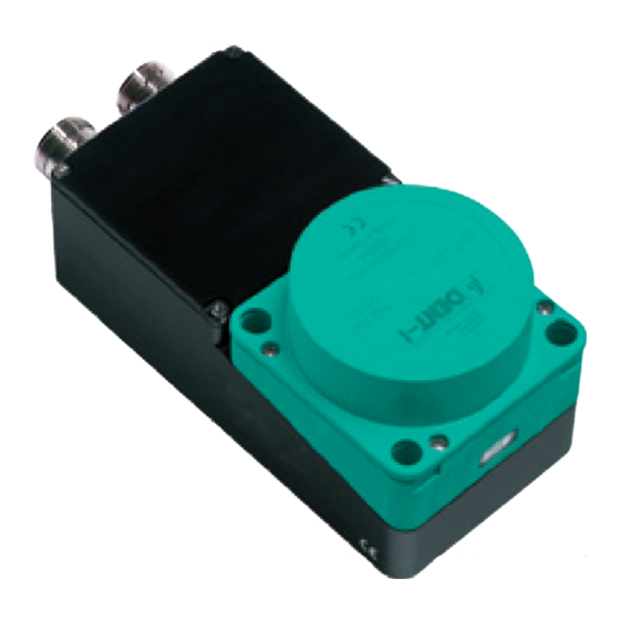
- Page 1 FACTORY AUTOMATION MANUAL IPT*-FP with U-P6-B5-V Read/write station with INTERBUS interface...
-
Page 2: Table Of Contents
IPT*-FP WITH U-P6-B5-V Introduction..............4 Declaration of conformity ...........5 CE conformity ................... 5 Safety................6 Symbols relevant to safety ..............6 Intended use....................6 General safety instructions..............6 Operational reliability and monitoring ............ 7 Product description.............8 Product family ................... 9 4.1.1 Code/data carrier ..................9 Range of application ................10 Delivery package..................10 Device characteristics ................10... - Page 3 IPT*-FP WITH U-P6-B5-V Commissioning ............17 Installation check ..................17 Preliminary considerations ..............18 Self test ....................18 Operation on the INTERBUS........19 General information on INTERBUS............19 Outline of the commands and data on the INTERBUS ......19 General command information ..............19 7.3.1 Software information .................19 7.3.2 Command overview...................21 System commands..................23...
-
Page 4: Introduction
Introduction Introduction Congratulations You have chosen a device manufactured by Pepperl+Fuchs. Pepperl+Fuchs develops, produces and distributes electronic sensors and interface modules for the market of automation technology on a worldwide scale. Before you install this device and put it into operation, please read the operating instructions thoroughly. -
Page 5: Declaration Of Conformity
IPT*-FP WITH U-P6-B5-V Declaration of conformity Declaration of conformity CE conformity This product was developed and manufactured under observance of the applicable European standards and guidelines. Note! A declaration of conformity can be requested from the manufacturer. -
Page 6: Safety
If serious faults occur, stop using the device. Secure the device against inadvertent operation. In the event of repairs, send the device to Pepperl+Fuchs. The connection of the device and maintenance work when live may only be carried out by a qualified electrical specialist. -
Page 7: Operational Reliability And Monitoring
IPT*-FP WITH U-P6-B5-V Safety Operational reliability and monitoring The devices IPT*-FP and U-P6-B5-V of the inductive identification system IDENT-I system P operate on a microprocessor level. Device status is reported via LEDs on the front side on the IPT*-FP read station and in the U-P6-B5-V lower section terminal compartment. In addition, the INTERBUS functionality can be tested by querying the status information or via specific commands to test the device. -
Page 8: Product Description
IPT*-FP WITH U-P6-B5-V Product description Product description The brand name IDENT-I System P represents a complete identification system. The read/write station consists of the read/write head IPT*-FP (standard version: IPT1-FP) and the lower section U-P6-B5-V with INTERBUS interface. With the use of 125 kHz technology, the system is extensively open for the implementation of other components. -
Page 9: Product Family
IPT*-FP WITH U-P6-B5-V Product description Product family The inductive identification system IDENT-I system P from Pepperl+Fuchs offers various possible combinations of individual components. Read/write station Lower sections Code/data carrier Note! Detailed information on the components of the identification system IDENT-I system P can be found in the sensor systems 1 catalog. -
Page 10: Range Of Application
IPT*-FP WITH U-P6-B5-V Product description Range of application The system is suited for the following applications: • Automation • Material flow control in production • Acquisition of operating data • Access control • Identification of e.g. storage vessels, pallets, work piece carriers, refuse containers, tanks, containers, etc. -
Page 11: Display And Controls
IPT*-FP WITH U-P6-B5-V Product description Display and controls The following displays and controls are located on the read/write head. LED display Bus error - red IPC recognized - yellow, command executed successfully (approx. 1 second) Power on - green Diagnostic LEDs The following diagnostic LEDs are located in the terminal compartment of the lower section: Color Meaning... -
Page 12: Interfaces And Connections
IPT*-FP WITH U-P6-B5-V Product description Interfaces and connections The following interfaces and connections are located on the lower section U-P6-B5-V: incoming interface outgoing interface /DO1 /DO2 /DI1 /DI2 +24 V +24 V /RBST connector socket... -
Page 13: Installation
Retain the original packaging in case the device must be stored or shipped again at a later date. Should you have any questions, please direct them to Pepperl+Fuchs. EMC screening The screening of cables provides for the discharge of electromagnetic interference. When screening a cable, both sides of the screen must be connected to the earth with low resistance and low inductance. -
Page 14: Device Connection
IPT*-FP WITH U-P6-B5-V Installation Device connection 5.4.1 Voltage supply The electrical connection of the lower section is made via M23 round connector. The assignment of the individual pins is shown in the connection diagram. incoming interface outgoing interface /DO1 /DO2 /DI1 /DI2 +24 V... -
Page 15: Earth Connection
IPT*-FP WITH U-P6-B5-V Installation 5.4.2 Earth connection The internal PE connection of the lower section is conductively connected with the housing. However, from the point of view of screening, connection to the outside of the housing is preferable. The external earth connection of the lower section is located lower left, adjacent to the round connectors. -
Page 16: Cable Lengths
IPT*-FP WITH U-P6-B5-V Installation 5.4.4 Cable lengths Depending on the type of cable used and the magnitude of the external interference, the total expansion of an INTERBUS installation remote bus can be up to 50 m. The number of devices connected to the bus is limited to 512. -
Page 17: Commissioning
IPT*-FP WITH U-P6-B5-V Commissioning Commissioning Warning! Before commissioning, ensure that the plant is not in danger relating to device malfunction, e.g. from uncontrollable triggered processes. Installation check Caution! Before commissioning, check once again that the connections are correct. Before commissioning, familiarize yourself with the system of communication between your INTERBUS and the read/write station. -
Page 18: Preliminary Considerations
IPT*-FP WITH U-P6-B5-V Commissioning Preliminary considerations Due to the complexity of field bus programming with the INTERBUS it is very difficult to make generally valid statements about commissioning. A very important aspect of the operation of an inductive identification system with the lower section on the INTERBUS is the time response of the overall system. -
Page 19: Operation On The Interbus
IPT*-FP WITH U-P6-B5-V Operation on the INTERBUS Operation on the INTERBUS General information on INTERBUS The INTERBUS is a standardized field bus, which enables data exchange between PLCs, PCs, operating and observation devices and also sensors and actuators. For detailed information, reference should be made to the INTERBUS standard DIN 19258 and to the current literature on the subject. - Page 20 IPT*-FP WITH U-P6-B5-V Operation on the INTERBUS Input data field: Byte 0 Command code (Echo) Byte 1 Parameter/Toggle flag (Echo) Byte 2 Status Byte 3 Execution counter Byte 4 Read data Byte N Read data (defined by module selection) In order to send a new command to the device, the INTERBUS master must write a command in the output data field.
-
Page 21: Command Overview
IPT*-FP WITH U-P6-B5-V Operation on the INTERBUS 7.3.2 Command overview The commands in the list are described in detail on the following pages. System commands Abbrevi Command code Command description ation quit change tag version Standard read/write commands Fixcode Abbrevi Command code Command description ation... - Page 22 IPT*-FP WITH U-P6-B5-V Operation on the INTERBUS Special command modes Password mode with IPC03 Abbrevi Command code Command description ation password mode password change password set IPC03 configuration Abbrevi Command code Command description ation single write configuration auto write configuration buffered write configuration 102d enhanced buffered write configuration...
-
Page 23: System Commands
IPT*-FP WITH U-P6-B5-V Operation on the INTERBUS System commands Quit Byte Content Byte 0 Command code Byte 1 Reserved/Toggle bit Byte 2 not relevant Byte 9 not relevant Response: Byte Content Byte 0 Command code Byte 1 Reserved/Toggle bit Byte 2 Status <Status>... -
Page 24: Response
IPT*-FP WITH U-P6-B5-V Operation on the INTERBUS Change Tag Byte Content Byte 0 Command code Byte 1 Reserved/Toggle bit Byte 2 Data carrier type in ASCII <TagType> (High Byte) Byte 3 Data carrier type in ASCII <TagType> (Low Byte) Byte 4 not relevant Byte 9 not relevant... - Page 25 IPT*-FP WITH U-P6-B5-V Operation on the INTERBUS Version Byte Content Byte 0 Command code Byte 1 Reserved/Toggle bit Byte 2 Parameter <Parameter> Byte 3 not relevant Byte 9 not relevant Response Byte Content Byte 0 Command code Byte 1 Reserved/Toggle bit Byte 2 Status <Status>...
-
Page 26: Read/Write Commands
IPT*-FP WITH U-P6-B5-V Operation on the INTERBUS Read/write commands 7.5.1 Read data Single Read Words Byte Content Byte 0 Command code Byte 1 Word count/Toggle bit <WordNum> Byte 2 Word address <WordAddr> (High Byte) Byte 3 Word address <WordAddr> (Low Byte) Byte 4 not relevant Byte 9... - Page 27 IPT*-FP WITH U-P6-B5-V Operation on the INTERBUS Auto Read Words Byte Content Byte 0 Command code Byte 1 Word count/Toggle bit <WordNum> Byte 2 Word address <WordAddr> (High Byte) Byte 3 Word address <WordAddr> (Low Byte) Byte 4 not relevant Byte 9 not relevant Response:...
- Page 28 IPT*-FP WITH U-P6-B5-V Operation on the INTERBUS Buffered Read Words Byte Content Byte 0 Command code Byte 1 Word count/Toggle bit <WordNum> Byte 2 Word address <WordAddr> (High Byte) Byte 3 Word address <WordAddr> (Low Byte) Byte 4 not relevant Byte 9 not relevant Response:...
- Page 29 IPT*-FP WITH U-P6-B5-V Operation on the INTERBUS Enhanced buffered Read Words Byte Content Byte 0 Command code Byte 1 Word count/Toggle bit <WordNum> Byte 2 Word address <WordAddr> (High Byte) Byte 3 Word address <WordAddr> (Low Byte) Byte 4 not relevant Byte 9 not relevant Response:...
-
Page 30: Write Data
IPT*-FP WITH U-P6-B5-V Operation on the INTERBUS 7.5.2 Write data Single Write Words Byte Content Byte 0 Command code Byte 1 Word count/Toggle bit <WordNum> Byte 2 Word address <WordAddr> (High Byte) Byte 3 Word address <WordAddr> (Low Byte) Byte 4 Data 00 ... - Page 31 IPT*-FP WITH U-P6-B5-V Operation on the INTERBUS Auto Write Words Byte Content Byte 0 Command code Byte 1 Word count/Toggle bit <WordNum> Byte 2 Word address <WordAddr> (High Byte) Byte 3 Word address <WordAddr> (Low Byte) Byte 4 Data 00 ... FF <Data 3>...
- Page 32 IPT*-FP WITH U-P6-B5-V Operation on the INTERBUS Buffered Write Words Byte Content Byte 0 Command code Byte 1 Word count/Toggle bit <WordNum> Byte 2 Word address <WordAddr> (High Byte) Byte 3 Word address <WordAddr> (Low Byte) Byte 4 Data 00 ... FF <Data 3>...
- Page 33 IPT*-FP WITH U-P6-B5-V Operation on the INTERBUS Enhanced Buffered Write Words Byte Content Byte 0 Command code Byte 1 Word count/Toggle bit <WordNum> Byte 2 Word address <WordAddr> (High Byte) Byte 3 Word address <WordAddr> (Low Byte) Byte 4 Data 00 ... FF <Data 3>...
-
Page 34: Read Only Code
IPT*-FP WITH U-P6-B5-V Operation on the INTERBUS Read only code Single Read Fixcode Byte Content Byte 0 Command code Byte 1 Reserved/Toggle bit Byte 2 not relevant Byte 9 not relevant Response: Byte Content Byte 0 Command code Byte 1 Reserved/Toggle bit Byte 2 Status... - Page 35 IPT*-FP WITH U-P6-B5-V Operation on the INTERBUS Auto Read Fixcode Byte Content Byte 0 Command code Byte 1 Reserved/Toggle bit Byte 2 not relevant Byte 9 not relevant Response: Byte Content Byte 0 Command code Byte 1 Reserved/Toggle bit Byte 2 Status <Status>...
- Page 36 IPT*-FP WITH U-P6-B5-V Operation on the INTERBUS Buffered Read Fixcode Byte Content Byte 0 Command code Byte 1 Reserved/Toggle bit Byte 2 not relevant Byte 9 not relevant Response: Byte Content Byte 0 Command code Byte 1 Reserved/Toggle bit Byte 2 Status <Status>...
- Page 37 IPT*-FP WITH U-P6-B5-V Operation on the INTERBUS Enhanced Buffered Read Fixcode Byte Content Byte 0 Command code Byte 1 Reserved/Toggle bit Byte 2 not relevant Byte 9 not relevant Response: Byte Content Byte 0 Command code Byte 1 Reserved/Toggle bit Byte 2 Status <Status>...
-
Page 38: Special Command Modes
IPT*-FP WITH U-P6-B5-V Operation on the INTERBUS Special command modes 7.7.1 IPC03 configuration Note! These commands can only be used when data carrier type 03 (IPC03) is set. They cannot be used in the autodetect mode (mixed operation, data carrier type 00)! The storage of a type IPC03 data carrier is organized by word. - Page 39 IPT*-FP WITH U-P6-B5-V Operation on the INTERBUS Protection word Meaning Byte 0 ... 7 First read-protected word 8 ... 15 Last read-protected word 16 ... 23 First write-protected word 24 ... 31 Last write-protected word With the control and protection word, it should be noted that when communicating a word, the highest value byte is transferred first and the lowest value byte last.
- Page 40 IPT*-FP WITH U-P6-B5-V Operation on the INTERBUS The start and end of the read range are stored in the bytes 0 and 1 of the "control word". As soon as the data carrier is supplied with energy the data carrier sends out the data from the data range, which is defined by the read range start and end.
- Page 41 IPT*-FP WITH U-P6-B5-V Operation on the INTERBUS Auto Write Configuration Byte Content Byte 0 Command code Byte 1 Reserved/Toggle bit Byte 2 not relevant Byte 3 Address in the configuration <RegAddr> range Byte 4 Data 00 ... FF <Data> Byte 5 Data 00 ...
- Page 42 IPT*-FP WITH U-P6-B5-V Operation on the INTERBUS Buffered Write Configuration Byte Content Byte 0 Command code Byte 1 Reserved/Toggle bit Byte 2 not relevant Byte 3 Address in the configuration <RegAddr> range Byte 4 Data 00 ... FF <Data> Byte 5 Data 00 ...
- Page 43 IPT*-FP WITH U-P6-B5-V Operation on the INTERBUS Enhanced Buffered Write Configuration Byte Content Byte 0 Command code Byte 1 Reserved/Toggle bit Byte 2 not relevant Byte 3 Address in the configuration <RegAddr> range Byte 4 Data 00 ... FF <Data> Byte 5 Data 00 ...
- Page 44 IPT*-FP WITH U-P6-B5-V Operation on the INTERBUS Single Get Configuration Byte Content Byte 0 Command code Byte 1 Reserved/Toggle bit Byte 2 Reserved Byte 3 Register address <RegAddr> Byte 4 not relevant Byte 9 not relevant Response: Byte Content Byte 0 Command code Byte 1 Reserved/Toggle bit...
- Page 45 IPT*-FP WITH U-P6-B5-V Operation on the INTERBUS Auto Get Configuration Byte Content Byte 0 Command code Byte 1 Reserved/Toggle bit Byte 2 Reserved Byte 3 Register address <RegAddr> Byte 4 not relevant Byte 9 not relevant Response: Byte Content Byte 0 Command code Byte 1 Reserved/Toggle bit...
- Page 46 IPT*-FP WITH U-P6-B5-V Operation on the INTERBUS Buffered Get Configuration Byte Content Byte 0 Command code Byte 1 Reserved/Toggle bit Byte 2 Reserved Byte 3 Register address <RegAddr> Byte 4 not relevant Byte 9 not relevant Response: Byte Content Byte 0 Command code Byte 1 Reserved/Toggle bit...
- Page 47 IPT*-FP WITH U-P6-B5-V Operation on the INTERBUS Enhanced Buffered Get Configuration Byte Content Byte 0 Command code Byte 1 Reserved/Toggle bit Byte 2 Reserved Byte 3 Register address <RegAddr> Byte 4 not relevant Byte 9 not relevant Response: Byte Content Byte 0 Command code Byte 1...
-
Page 48: Password Mode With Ipc03
IPT*-FP WITH U-P6-B5-V Operation on the INTERBUS 7.7.2 Password mode with IPC03 Note! The password is a 32-bit word that is set to "0" before a new IPC03 data carrier leaves the factory. The password cannot be read. In order to write the passwords for the "Control Word" and the "Protection Word", the processing must always be in password mode. - Page 49 IPT*-FP WITH U-P6-B5-V Operation on the INTERBUS Password Change Byte Content Byte 0 Command code Byte 1 Reserved/Toggle bit Byte 2 Old password 00 ... FF <PSW 3> Byte 3 Old password 00 ... FF <PSW 2> Byte 4 Old password 00 ... FF <PSW 1>...
- Page 50 IPT*-FP WITH U-P6-B5-V Operation on the INTERBUS Password Set Byte Content Byte 0 Command code Byte 1 Reserved/Toggle bit Byte 2 not relevant Byte 3 not relevant Byte 4 Password 00 ... FF <PSW 3> Byte 5 Password 00 ... FF <PSW 2>...
-
Page 51: Write Fixed Code Ipc10
IPT*-FP WITH U-P6-B5-V Operation on the INTERBUS 7.7.3 Write fixed code IPC10 Single Write Fixcode Byte Content Byte 0 Command code Byte 1 FixLen/Toggle bit <FixLen> Byte 2 Fixtype <FixType> (High Byte) Byte 3 Fixtype <FixType> (Low Byte) Byte 4 Data 00 ... - Page 52 IPT*-FP WITH U-P6-B5-V Operation on the INTERBUS Auto Write Fixcode Byte Content Byte 0 Command code Byte 1 FixLen/Toggle bit <FixLen> Byte 2 FixType <FixType> (High Byte) Byte 3 FixType <FixType> (Low Byte) Byte 4 Data 00 ... FF <Data> Data 00 ...
- Page 53 IPT*-FP WITH U-P6-B5-V Operation on the INTERBUS Buffered Write Fixcode Byte Content Byte 0 Command code Byte 1 FixLen/Toggle bit <FixLen> Byte 2 FixType <FixType> (High Byte) Byte 3 FixType <FixType> (Low Byte) Byte 4 Data 00 ... FF <Data> Data 00 ...
- Page 54 IPT*-FP WITH U-P6-B5-V Operation on the INTERBUS Enhanced buffered write fixed code; write ID code Byte Content Byte 0 Command code Byte 1 FixLen/Toggle bit <FixLen> Byte 2 Fixtype <FixType> (High Byte) Byte 3 Fixtype <FixType> (Low Byte) Byte 4 Data 00 ...
-
Page 55: Legend
IPT*-FP WITH U-P6-B5-V Operation on the INTERBUS Legend <ConfAddr> Word start address in the configuration range of the data carrier. 1 ASCII character range from "0" to "F", depending on data carrier type. The following applies for IPC03: "1" = Protection Word "2"... -
Page 56: Error/Status Messages
IPT*-FP WITH U-P6-B5-V Operation on the INTERBUS Error/Status messages Status Meaning The command has been executed without error. The command is processing. Error messages which triggered the identification system Status Meaning Switch-on message. Reset has been executed. Reserved Incorrect or incomplete command or parameter not in the valid range. -
Page 57: Technical Specifications
IPT*-FP WITH U-P6-B5-V Technical specifications Technical specifications Read/write station IPT*-FP IPT*-FP General data Operating frequency 125 kHz Transfer rate 2 kBit/s Operating distance max. 100 mm Display/controls LED green Power on LED yellow IPC recognized LED red Bus error (with the use of field bus interfaces) Electrical data Rated operating voltage U... -
Page 58: Read/Write Distances Ipt*-Fp
IPT*-FP WITH U-P6-B5-V Technical specifications Dimensions of the read/write station Read/write distances IPT*-FP Distances Data carrier type in air Read distance with IPC02-20W 0 mm...40 mm Read distance with IPC02-30W 0 mm...50 mm Read distance with IPC02-50W 0 mm...80 mm Read distance with IPC02-C1 0 mm...80 mm... -
Page 59: U-P6-B5-V Lower Section
IPT*-FP WITH U-P6-B5-V Technical specifications U-P6-B5-V lower section U-P6-B5 Electrical data Rated operating voltage 20 ... 30 V DC, ripple 10 % , PELV Current loading < 300 mA (U = 24 V) with read/write station Power consumption P max. 5 W with read/write station Galvanic isolation Operating Functional isolation in accordance with DIN EN 50178, rated... - Page 60 IPT*-FP WITH U-P6-B5-V Technical specifications U-P6-B5-V Lower section +0.2 10° Ø9.5 Ø5.3 ±0.2 32.5 ±0.3 32.5 ±0.3 22.3 ±0.2 Electrical connection incoming interface outgoing interface /DO1 /DO2 /DI1 /DI2 +24 V +24 V /RBST connector socket...
- Page 61 IPT*-FP WITH U-P6-B5-V Technical specifications...
- Page 62 Twinsburg, Ohio 44087 · USA Tel. +1 330 4253555 E-mail: sales@us.pepperl-fuchs.com Asia Pacific Headquarters Pepperl+Fuchs Pte Ltd. Company Registration No. 199003130E Singapore 139942 Tel. +65 67799091 E-mail: sales@sg.pepperl-fuchs.com www.pepperl-fuchs.com Subject to modifications TDOCT-1417_ENG 205842 Copyright PEPPERL+FUCHS • Printed in Germany 03/2009...
Need help?
Do you have a question about the IDENT-I system P IPT FP Series and is the answer not in the manual?
Questions and answers