GORMAN-RUPP PUMPS 10 Series Installation, Operation And Maintenance Manual
Hide thumbs
Also See for 10 Series:

Related Manuals for GORMAN-RUPP PUMPS 10 Series


Summary of Contents for GORMAN-RUPP PUMPS 10 Series
- Page 1 COM‐07291-01 September 16, 2019 INSTALLATION, OPERATION, AND MAINTENANCE MANUAL WITH PARTS LIST 10 SERIES PUMP MODEL 14C2-4LE2T FT4 GORMAN‐RUPP PUMPS www.grpumps.com 2019 Gorman‐Rupp Pumps Printed in U.S.A.
- Page 2 Register your new Gorman‐Rupp pump online at www.grpumps.com Valid serial number and e‐mail address required. The engine exhaust from this product contains chemicals known to the State of California to cause cancer, birth defects or other reproductive harm. RECORD YOUR PUMP MODEL AND SERIAL NUMBER Please record your pump model and serial number in the spaces provided below.
-
Page 3: Table Of Contents
TABLE OF CONTENTS INTRODUCTION ........... PAGE I - 1 SAFETY - SECTION A . - Page 4 TABLE OF CONTENTS (continued) BEARING TEMPERATURE CHECK ......... . PAGE C - 4 TROUBLESHOOTING - SECTION D .
-
Page 5: Introduction
10 SERIES OM-07291 INTRODUCTION Thank You for purchasing a Gorman‐Rupp pump. HAZARD AND INSTRUCTION Read this manual carefully to learn how to safely DEFINITIONS install and operate your pump. Failure to do so could result in personal injury or damage to the The following are used to alert maintenance per... -
Page 6: Safety - Section A
10 SERIES OM-07291 SAFETY - SECTION A This information applies to 10 Series en pump or endanger personnel as a result of pump failure. gine driven pumps. Refer to the manual accompanying the engine before at tempting to begin operation. - Page 7 10 SERIES OM-07291 heated pump. Vapor pressure within the pump can cause parts being disen gaged to be ejected with great force. Al low the pump to cool before servicing. Fuel used by internal combustion en gines presents an extreme explosion and fire hazard.
-
Page 8: Installation - Section B
10 SERIES OM-07291 INSTALLATION - SECTION B Review all SAFETY information in Section A. to the pump is critical to performance and safety, be sure to limit the incoming pressure to 50% of Since pump installations are seldom identical, this... -
Page 9: Battery Specifications And Installation
OM-07291 10 SERIES c. Carefully read all warnings and cautions con POSITIONING PUMP tained in this manual or affixed to the pump, and perform all duties indicated. Lifting d. Check levels and lubricate as necessary. Re fer to LUBRICATION in the MAINTENANCE AND REPAIR section of this manual and per... -
Page 10: Clearance
10 SERIES OM-07291 only; however, the engine manufacturer should be to secure them when filled with liquid and under consulted for continuous operation at angles pressure. greater than 15 Gauges Clearance Most pumps are drilled and tapped for installing discharge pressure and vacuum suction gauges. If... -
Page 11: Sealing
OM-07291 10 SERIES Sealing of the suction pipe. The baffle will allow entrained air to escape from the liquid before it is drawn into Since even a slight leak will affect priming, head, the suction inlet. and capacity, especially when operating with a... -
Page 12: Discharge Lines
10 SERIES OM-07291 In low discharge head applications (less than 30 DISCHARGE LINES feet (9,1 m)), it is recommended that the bypass line be run back to the wet well, and located 6 Siphoning inches below the water level or cut‐off point of the low level pump. -
Page 13: Automatic Air Release Valve
OM-07291 10 SERIES Figures 4 and 5 show a cross‐sectional view of the Automatic Air Release Valve, and a corresponding description of operation. During the priming cycle, air from the pump casing flows through the bypass A manual shut‐off valve should not be line, and passes through the Air Release Valve to installed in any bypass line. -
Page 14: Air Release Valve Installation
10 SERIES OM-07291 ny for information about an Automatic Air Release connected to the discharge line of the self‐priming Valve for your specific application. centrifugal pump (see Figure 6). NOTE Air Release Valve Installation If the Air Release Valve is to be installed on a staged pump application, contact the factory for specific installation instructions. -
Page 15: Operation - Section C
OM-07291 10 SERIES OPERATION - SECTION C OPERATION Make sure the pump is level. Lower the jack stands and chock the wheels, if so equipped. Review all SAFETY information in Section A. Follow the instructions on all tags, labels and decals attached to the pump. -
Page 16: Lines With A Bypass
OM-07291 10 SERIES shut‐off valve may inadvertently be left closed during operation. A pump which has lost prime may continue to operate without reaching prime, causing dan After filling the pump casing, reinstall gerous overheating and possible explo and tighten the fill plug. Do not attempt sive rupture of the pump casing. -
Page 17: Leakage
OM-07291 10 SERIES operation manual for the recommended lubricant ter the pump cools, drain the liquid from for operation in extreme heat. the pump by removing the casing drain plug. Use caution when removing the plug to prevent injury to personnel from OPERATIONAL CHECKS hot liquid. -
Page 18: Cold Weather Preservation
OM-07291 10 SERIES tenance and Repair). Bearing overheating can also be caused by shaft misalignment and/or ex cessive vibration. Never disconnect any of the safety shut When pumps are first started, the bearings may down features; this will void the warran... - Page 19 10 SERIES OM-07291 TROUBLESHOOTING - SECTION D Review all SAFETY information in Section A. to ensure that the pump will remain inoperative. 3. Allow the pump to completely cool if overheated. 4. Check the temperature before opening any covers, plates, or Before attempting to open or service the plugs.
- Page 20 OM-07291 10 SERIES Table 1. Trouble Shooting Chart (cont.) TROUBLE POSSIBLE CAUSE PROBABLE REMEDY PUMP STOPS OR FAILS Leaking or worn seal or pump gas Check pump vacuum. Replace ket. leaking or worn seal or gasket. TO DELIVER RATED FLOW OR PRESSURE Strainer clogged.
- Page 21 10 SERIES OM-07291 Table 1. Trouble Shooting Chart (cont.) TROUBLE POSSIBLE CAUSE PROBABLE REMEDY BEARINGS RUN TOO Bearing temperature is high, but Check bearing temperature regular within limits. ly to monitor any increase. Low or incorrect lubricant. Check for proper type and level of lubricant.
- Page 22 OM-07291 10 SERIES Preventive Maintenance Schedule Service Interval* Item Daily Weekly Monthly Semi‐ Annually Annually General Condition (Temperature, Unusual Noises or Vibrations, Cracks, Leaks, Loose Hardware, Etc.) Pump Performance (Gauges, Speed, Flow) Bearing Lubrication Seal Lubrication (And Packing Adjustment, If So Equipped) V‐Belts (If So Equipped)
- Page 23 OM-07291 10 SERIES PUMP MAINTENANCE AND REPAIR - SECTION E MAINTENANCE AND REPAIR OF THE WEARING PARTS OF THE PUMP WILL MAINTAIN PEAK OPERATING PERFORMANCE. STANDARD PERFORMANCE FOR PUMP MODEL 14C2-4LE2T FT4 Based on 70 F (21 C) clear water at sea level Contact the Gorman‐Rupp Company to verify per...
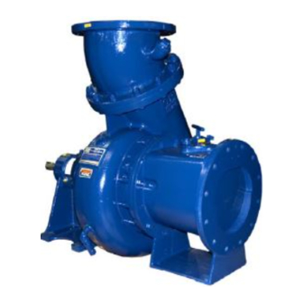
- Page 24 OM-07291 10 SERIES PARTS PAGE ILLUSTRATION Figure 1. Pump Model 14C2-4LE2T FT4 PAGE E - 2 MAINTENANCE & REPAIR...
- Page 25 OM-07291 10 SERIES PARTS LIST Pump Model 14C2-4LE2T FT4 (From S/N and 1706176 Up ) If your pump serial number is followed by an “N”, your pump is NOT a standard production model. Contact the Gorman‐Rupp Company to verify part numbers.
- Page 26 OM-07291 10 SERIES ILLUSTRATION Figure 2. 46143-229 Power Unit Kit PAGE E - 4 MAINTENANCE & REPAIR...
- Page 27 OM-07291 10 SERIES PARTS LIST 46143-229 Power Unit Kit ITEM PART MAT'L PART NAME NUMBER CODE BASE/FUEL TANK 41553-029 24150 LIFTING BAIL KIT 48274-811 ISUZU DIESEL ENGINE 4LE2T FT4 29223-402 STUD MOUNT 24631-014 HEX NUT 15991 LOCKWASHER 15991 CONTROL PANEL...
- Page 28 OM-07291 10 SERIES ILLUSTRATION Figure 3. 14C2-(SAE4/10) Pump End Assy PAGE E - 6 MAINTENANCE & REPAIR...
- Page 29 OM-07291 10 SERIES PARTS LIST 14C2-(SAE4/10) Pump End Assy ITEM PART NAME PART MAT'L ITEM PART NAME PART MAT'L NUMBER CODE NUMBER CODE PUMP CASING SEE NOTE BELOW LOCKWASHER 15991 HEX NUT 15991 IMPELLER 9934A 11060 CLAMP BAR 12064 11010...
- Page 30 OM-07291 10 SERIES ILLUSTRATION Figure 4. 14C2-(SAE 4/10) Drive Assembly PARTS LIST ITEM PART MAT'L PART NAME NUMBER CODE COUPLING KIT 48112-001 -BUSHING 24131-345 -COUPLING ASSEMBLY 44165-011 -LOCKWASHER 21171-536 ALTERNATE PARTS: -SOCKET HD CAPSCREW BD0606 1/2 15991 -SOCKET HD CAPSCREW...
- Page 31 OM-07084 10 SERIES PUMP AND SEAL DISASSEMBLY AND REASSEMBLY Before attempting to open or service the pump: Review all SAFETY information in Section A. 1. Familiarize yourself with this man ual. 2. Switch off the engine ignition and Follow the instructions on all tags, label and de...
- Page 32 OM-07084 10 SERIES may be serviced by removing the back cover as fully engaged. Support the pump using a suitable sembly (49). hoist and the lifting eye. Remove the cover clamp screw (46) and clamp bar Remove the hardware (6 and 7) securing the inter...
- Page 33 OM-07084 10 SERIES shaft (26) with the “V” notch positioned over the Remove the nuts (38) securing the pump casing to shaft key. the intermediate (19). Use the hoist and sling to separate the intermediate and rotating portion of With the impeller rotation still blocked, see Figure 5 the pump from the pump casing.
- Page 34 OM-07084 10 SERIES Inspect the seal liner (74) for wear or grooves strongly recommended that the bearings which could cause leakage or damage to the seal be replaced any time the shaft and bear packing rings. The seal liner is a press fit in the seal ings are removed.
- Page 35 OM-07084 10 SERIES small nicks and burrs with a fine file or emery cloth. away from the shaft shoulders in shrinking. If Replace the shaft if defective. movement has occurred, use a suitably sized sleeve and a press to reposition the bearings against the shaft shoulders.
- Page 36 OM-07084 10 SERIES Securing Intermediate And Drive Assembly To the engine flywheel by torquing the hardware to 45 Engine ft. lbs. (540 in. lbs. or 6,2 m. kg.). (Figure 4) Using a suitable lifting device, position the as sembled coupling, intermediate, shaft and bear...
- Page 37 OM-07084 10 SERIES Inspect the seal components for wear, scoring, faces to ensure that they are free of any foreign grooves, and other damage that might cause leak matter. age. Clean and polish the seal liner, or replace it if there are nicks or cuts on either end.
- Page 38 OM-07084 10 SERIES the stationary seal seats, packing rings, stationary ance, and add or remove impeller adjusting shims washers, and spring onto the lubricated shaft as required. sleeve. Apply a drop of light oil on the precision fin NOTE ished faces of the stationary seats; never use If the pump has been completely disassembled, it grease.
- Page 39 OM-07084 10 SERIES NOTE Secure the back cover assembly by tightening the cover clamp screw (46) against the clamp bar (45). The check valve assembly must be replaced as a Do not over‐tighten the clamp screw; it should be complete unit. Individual parts are not sold sepa...
- Page 40 OM-07084 10 SERIES POSITION POSITION POSITION WHEN WHEN EMPTY FILLING IN USE GREASE FITTING CROSS RELIEF HOLE NOTE: When installing a new grease cup, lubricate the cup as indicated on the installation tag furnished with the grease cup. Figure . Automatic Lubricating Grease Cup...
- Page 41 For Warranty Information, Please Visit www.grpumps.com/warranty or call: U.S.: 419-755-1280 Canada: 519-631-2870 International: +1-419-755-1352 GORMAN‐RUPP PUMPS...
Need help?
Do you have a question about the 10 Series and is the answer not in the manual?
Questions and answers