Table of Contents
Advertisement
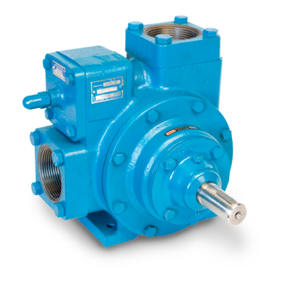
BLACKMER TRUCK PUMPS
INSTALLATION OPERATION AND MAINTENANCE INSTRUCTIONS
MODELS: TX, TXD - 1.5, 2A, 2.5A, 3E, 4A
Numbers in parentheses following individual parts
indicate reference numbers on Blackmer Parts Lists
201-A01, 201-A02, 201-A03, 201-A04 and 201-A05.
Blackmer pump manuals and parts lists may be
obtained from Blackmer's website (www.blackmer.com)
or by contacting Blackmer Customer Service.
This is a SAFETY ALERT SYMBOL.
When you see this symbol on the product, or in the
manual, look for one of the following signal words and be
alert to the potential for personal injury, death or major
property damage
Warns of hazards that WILL cause serious personal injury,
death or major property damage.
Warns of hazards that CAN cause serious personal injury,
death or major property damage.
Warns of hazards that CAN cause personal injury
or property damage.
NOTICE:
Indicates special instructions which are very
important and must be followed.
TABLE OF CONTENTS
Technical Data ....................................................... 2
Initial Pump Start Up Information ........................... 2
Pre-Installation Cleaning ........................................ 3
Location and Piping ............................................... 3
Truck Mounting ...................................................... 3
Pump Drive ............................................................ 3
Pump Rotation ....................................................... 4
To Change Pump Rotation .................................... 4
Pre-Start Up Check List ......................................... 5
Start Up Procedures .............................................. 5
Pump Speed .......................................................... 5
Reverse Rotation ................................................... 5
Flushing the Pump ................................................. 6
Pump Relief Valve ................................................. 6
Relief Valve Setting and Adjustment...................... 6
Strainers ................................................................ 7
Lubrication ............................................................. 7
Vane Replacement ................................................ 8
Pump Disassembly ................................................ 8
Pump Assembly ..................................................... 9
TROUBLE SHOOTING ......................................
SAFETY DATA
Blackmer Truck Pumps MUST only be installed in systems,
which have been designed by qualified engineering
personnel.
local and national regulations and safety standards.
This manual is intended to assist in the installation and
operation of the Blackmer truck pumps, and MUST be kept
with the pump.
Pump service shall be performed by qualified technicians
ONLY.
Service shall conform to all applicable local and
national regulations and safety standards.
Thoroughly review this manual, all instructions and hazard
warnings, BEFORE performing any work on the pump.
Maintain ALL system and pump operation and hazard
warning decals.
960280
INSTRUCTIONS NO. 201-A00
Section
Effective
Replaces
NOTICE:
The system MUST conform to all applicable
201
May 2012
Jan 2012
Page
10
Advertisement
Table of Contents

Related Manuals for BLACKMER TX


Summary of Contents for BLACKMER TX
-
Page 1: Table Of Contents
960280 BLACKMER TRUCK PUMPS INSTRUCTIONS NO. 201-A00 INSTALLATION OPERATION AND MAINTENANCE INSTRUCTIONS Section Effective May 2012 MODELS: TX, TXD - 1.5, 2A, 2.5A, 3E, 4A Replaces Jan 2012 TABLE OF CONTENTS Page PUMP DATA Technical Data ............2 Initial Pump Start Up Information ......2 INSTALLATION Pre-Installation Cleaning ........ -
Page 2: Pump Data
A pump Identification tag, containing the pump serial number, I.D. number, and model designation, is attached to each pump. It is recommended that the data from this tag be recorded and filed for future reference. If replacement parts are needed, or if information pertaining to the pump is required, this data must be furnished to a Blackmer representative. TECHNICAL DATA... -
Page 3: Installation
The pump will operate satisfactorily in any position. Consult 3. Use an even number of universal joints. Blackmer factory for vertical shaft mounts. The pump can be bolted to the truck frame or on a saddle hung below the 4. The pump shaft and power take-off shaft must be parallel frame, and MUST be adequately supported. -
Page 4: Pump Rotation
Hydraulic motors need to be well supported with their shafts The TXD pump models are equipped with a double ended parallel to the pump shaft in all respects. Blackmer provides rotor and shaft, enabling them to be driven from either shaft an optional close-coupled hydraulic motor adapter. -
Page 5: Operation
OPERATION START UP PROCEDURES NOTICE: Consult the "General Pump Troubleshooting" section of Pumps operating against a closed this manual if difficulties during start up are experienced. valve can cause system failure, personal injury and property damage 1. Ensure that appropriate valves are open in the inlet and Hazardous pressure discharge lines. -
Page 6: Flushing The Pump
(i.e., waxes, adhesives, resins, asphalts, etc.), use a fluid that will prevent solidification of If the pump is equipped with a Blackmer air valve, refer to the fluid being transferred and facilitate flushing. setting and adjustment procedures in Blackmer Air Valve Instructions and Parts List No. -
Page 7: Maintenance
MAINTENANCE Failure to set the vehicle emergency Disconnecting fluid or pressure brake and chock wheels before containment components during pump performing service can cause severe operation can cause serious personal personal injury or property damage. injury, death or major property damage Hazardous pressure Hazardous pressure can cause personal... -
Page 8: Vane Replacement
MAINTENANCE VANE REPLACEMENT 4. If equipped with locknuts and lockwashers (24A, 24B): NOTICE: a. Bend up the engaged lockwasher tang and rotate the Maintenance shall be performed by qualified technicians locknut counterclockwise to remove it from the shaft. only, following the appropriate procedures and warnings b. -
Page 9: Pump Assembly
MAINTENANCE PUMP ASSEMBLY 9. Install the inboard head (20), mechanical seal, and bearing as instructed in steps 2 through 7. Apply a thin Before reassembling the pump, inspect all component coating of motor oil on the inboard shaft to aid installation. parts for wear or damage, and replace as required. -
Page 10: Troubleshooting
18. RELIEF VALVE ASSEMBLY a. Slide the lock collar (24A) over the shaft and against If the pump is equipped with a Blackmer air valve, refer to the bearing (24), with the counterbored side towards setting and adjustment procedures in Blackmer Air Valve the bearing. - Page 11 TROUBLESHOOTING continued Pump speed too low. Suction valves not fully open. Air leaks in the suction line. Excessive restriction in the suction line (i.e.: undersized piping, too many elbows & Reduced Capacity fittings, clogged strainer, etc.). Damaged or worn parts. Excessive restriction in discharge line causing partial flow through the relief valve.
- Page 12 Accessories Dispensing, Transfer, In-line Gear Reducers, Bypass Valves, Strainers Visit www.blackmer.com for complete information on all Blackmer products 1809 Century Avenue, Grand Rapids, Michigan 49503-1530 U.S.A. Telephone: (616) 241-1611 • Fax: (616) 241-3752 E-mail: blackmer@blackmer.com • Internet Address: www .blackmer.com...
Need help?
Do you have a question about the TX and is the answer not in the manual?
Questions and answers