Table of Contents
Advertisement
Quick Links
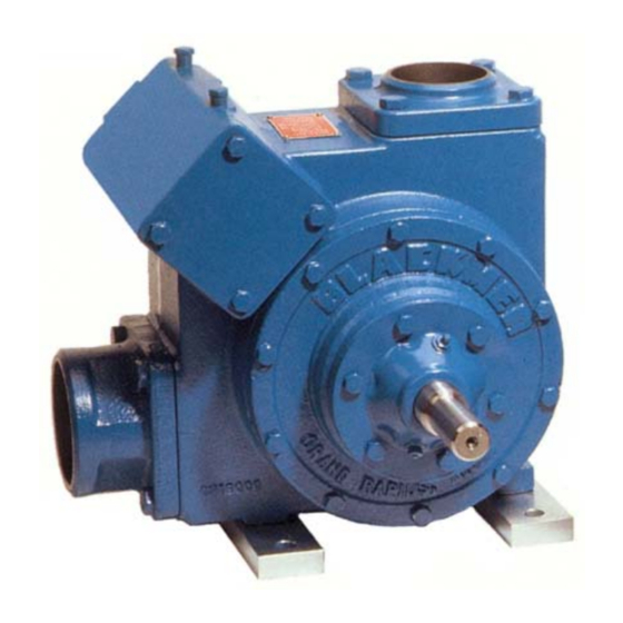
BLACKMER TRUCK PUMPS
INSTALLATION OPERATION AND MAINTENANCE INSTRUCTIONS
TRANSMAX
TABLE OF CONTENTS
Technical Data ................................................... 2
Initial Pump Start Up Information ....................... 2
.................................................. 3
Pre-Installation Cleaning .................................... 4
Location and Piping ........................................... 4
Truck Mounting .................................................. 4
Pump Drive ........................................................ 4
Pre-Start Up Check List ..................................... 5
Start Up Procedures .......................................... 5
Pump Speed ...................................................... 5
Reverse Rotation ............................................... 5
Flushing the Pump ............................................. 6
Pump Relief Valve ............................................. 6
Relief Valve Setting and Adjustment ................. 6
Strainers ............................................................ 7
Lubrication ......................................................... 7
Vane Replacement ............................................ 7
Pump Disassembly ............................................ 8
Parts Replacement ............................................ 8
Pump Assembly ................................................. 8
Numbers in parentheses following individual parts indicate
reference numbers on Blackmer Parts List No. 205-A02
Blackmer pump manuals and parts lists may be obtained from
Blackmer's website (www.blackmer.com) or by contacting
Blackmer Customer Service.
®
MODEL: TX400B
................................
Page
................................
10-11
SAFETY DATA
This is a SAFETY ALERT SYMBOL.
When you see this symbol on the product, or in the
manual, look for one of the following signal words and be
alert to the potential for personal injury, death or major
property damage
Warns of hazards that WILL cause serious personal injury,
death or major property damage.
Warns of hazards that CAN cause serious personal injury,
death or major property damage.
Warns of hazards that CAN cause personal injury
or property damage.
NOTICE:
Indicates special instructions which are very
important and must be followed.
NOTICE:
Blackmer Truck Pumps MUST only be installed in systems,
which have been designed by qualified engineering
personnel. The system MUST conform to all applicable
local and national regulations and safety standards.
This manual is intended to assist in the installation and
operation of the Blackmer TransMax truck pumps, and
MUST be kept with the pump.
Pump service shall be performed by qualified technicians
ONLY. Service shall conform to all applicable local and
national regulations and safety standards.
Thoroughly review this manual, all instructions and hazard
warnings, BEFORE performing any work on the pump.
Maintain ALL system and pump operation and hazard
warning decals.
961808
INSTRUCTIONS NO. 205-A00
Section
205
Effective
Jan 2014
Replaces
Aug 2010
Advertisement
Table of Contents

Subscribe to Our Youtube Channel
Related Manuals for BLACKMER TRANSMAX TX400B


Summary of Contents for BLACKMER TRANSMAX TX400B
-
Page 1: Table Of Contents
........ TROUBLE SHOOTING 10-11 warning decals. Numbers in parentheses following individual parts indicate reference numbers on Blackmer Parts List No. 205-A02 Blackmer pump manuals and parts lists may be obtained from Blackmer's website (www.blackmer.com) or by contacting Blackmer Customer Service. -
Page 2: Safety Data
If replacement parts are needed, or if information pertaining to the pump is required, this data must be furnished to a Blackmer representative. TECHNICAL DATA * INITIAL PUMP START UP INFORMATION Model No.:... -
Page 3: Pump Rotation & Porting Configurations
PUMP ROTATION AND PORTING CONFIGURATIONS Figure 1 – Port and Relief Valve Locations ROTATION DISCHARGE POSITION CW = Clockwise V = Vertical to foot CC = Counterclockwise H = Horizontal to foot INTAKE POSITION V = Vertical to foot H = Horizontal to foot TX400B pumps are equipped with a double-ended drive shaft. -
Page 4: Installation
The pump will operate satisfactorily in any position. Consult 4. The pump shaft and power take-off shaft must be parallel Blackmer factory for vertical shaft mounts. The pump can be in all respects. Use an angular level measuring device to... -
Page 5: Operation
OPERATION START UP PROCEDURES NOTICE: Operation without guards in place can Consult the "General Pump Troubleshooting" section of cause serious personal injury, major this manual if difficulties during start up are experienced. property damage, or death. 1. Ensure that appropriate valves are open in the inlet and Do not operate discharge lines. -
Page 6: Flushing The Pump
Replace the valve cap. Refer to the individual Blackmer pump parts lists for various spring pressure ranges. Unless specified otherwise, pumps are supplied from the factory with the relief valve adjusted to the mid-point of the spring range. -
Page 7: Maintenance
MAINTENANCE Failure to set the vehicle emergency Disconnecting fluid or pressure brake and chock wheels before containment components during pump performing service can cause severe operation can cause serious personal personal injury or property damage. injury, death or major property damage Hazardous pressure Hazardous pressure can cause personal... -
Page 8: Pump Disassembly
MAINTENANCE 7. Pull the rotor and shaft (13) from the cylinder. While one PUMP DISASSEMBLY hand is pulling the shaft, the other hand should be cupped NOTICE: underneath the rotor to prevent the vanes (14) and push rods (77) from falling out. Carefully set the rotor and shaft Follow all hazard warnings and instructions provided in aside for future vane replacement and reassembly. - Page 9 MAINTENANCE 3. LIP SEAL ASSEMBLY (if equipped) On pumps equipped with a lip seal, install two 3/8" (10 mm) washers and two bearing cover capscrews The lip seal assembly consists of a metal housing with elastomer(s) around its outer diameter(s), and a PTFE lip (28) to clamp the bearing and compress the lip seal housing inner O-ring for proper bearing locknut seal in its inner diameter.
-
Page 10: Troubleshooting
MAINTENANCE f. Tighten the opposite locknut by hand until it is snug 14. Follow steps 13 and 14 to install the grease seal and against the bearing. Then, using a spanner wrench, bearing cover (27A) on the opposite side of the pump. tighten the nut the width of one lockwasher tang. - Page 11 TROUBLESHOOTING ….. cont. Pump speed too low. Suction valves not fully open. Air leaks in the suction line. Excessive restriction in the suction line (i.e.: undersized piping, too many elbows & fittings, clogged strainer, etc.). Reduced Capacity Damaged or worn parts. Excessive restriction in discharge line causing partial flow through the relief valve.
- Page 12 Accessories Dispensing, Transfer, In-line Gear Reducers, Bypass Valves, Strainers Visit www.blackmer.com for complete information on all Blackmer products 1809 Century Avenue, Grand Rapids, Michigan 49503-1530 U.S.A. Telephone: (616) 241-1611 • Fax: (616) 241-3752 E-mail: blackmer@blackmer.com • Internet Address: www .blackmer.com...
Need help?
Do you have a question about the TRANSMAX TX400B and is the answer not in the manual?
Questions and answers